

Novel peristaltic pump head
A peristaltic pump and pump head technology, applied in the field of pump components, can solve problems such as increased cost consumption
- Summary
- Abstract
- Description
- Claims
- Application Information
AI Technical Summary
Problems solved by technology
Method used
Image

Examples
Embodiment Construction
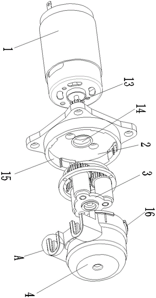
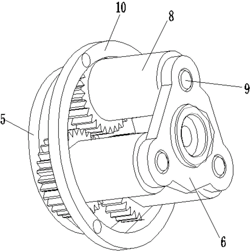
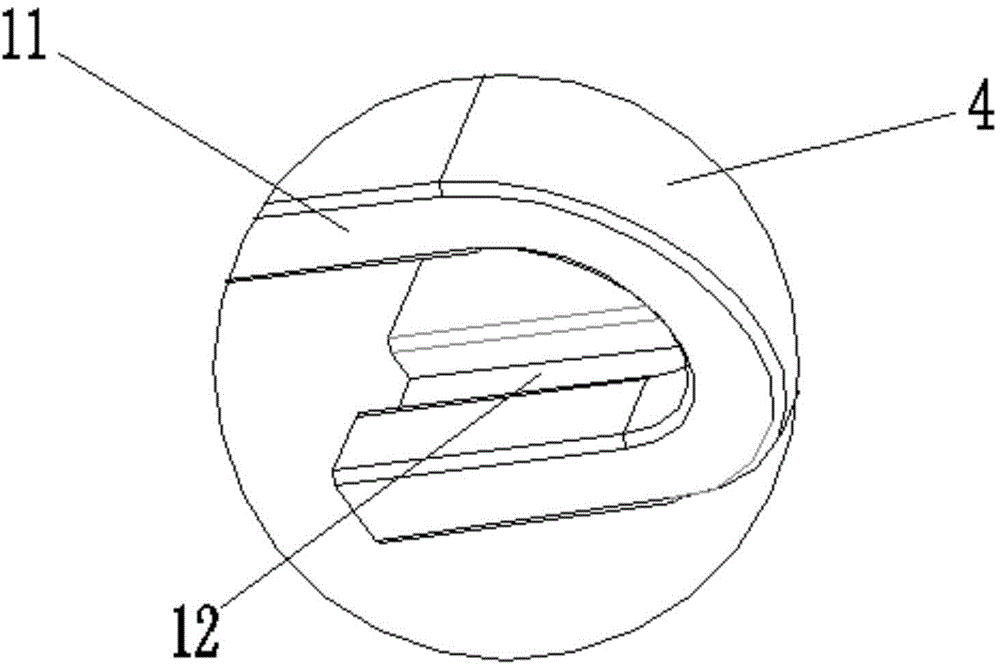
[0014] Such as figure 1 A new type of peristaltic pump head shown includes a micro motor 1, a pump head base 2, a roller assembly 3 and a pump head upper cover 4, the upper surface of the pump head base 2 is provided with grooves, and the The roller assembly 3 is located in the groove of the pump head base 2, the pump head upper cover 4 is connected above the pump head base 2, and the roller assembly 3 is located on the pump head base 2 and the pump head upper cover 4, a through hole 14 is opened at the center of the groove, and the shaft end of the micro motor 1 passes through the through hole 14 to engage with the roller assembly 3, and the shaft end of the micro motor 1 A first gear 13 is provided through which the micro motor 1 is connected with the roller assembly 3 , and two "U"-shaped inlet and outlet nozzles 11 are opened on one side of the pump head cover 4 . The side wall of the groove is provided with a card slot 15, and the outside of the pump head upper cover 4 i...
PUM
 Abstract
Description
Claims
Application Information