
Electronic equipment, and control method therefor

A technology of electronic equipment and control method, applied in the direction of current collectors, electric vehicles, electrical components, etc., can solve the problems of slow charging speed, small charging current, long charging time, etc., achieve fast charging speed, shorten charging time, and improve usage The effect of experience

Active Publication Date: 2015-09-02
LENOVO (BEIJING) LTD
View PDF7 Cites 16 Cited by
  • Summary
  • Abstract
  • Description
  • Claims
  • Application Information

AI Technical Summary

Problems solved by technology

[0002] At present, electronic devices with USB interfaces such as computers or mobile phones can use the charging function such as OTG (USB On-The-Go) function to charge other electronic devices with USB interfaces, but generally when charging external devices through USB interfaces The charging current is small, so the charging speed is relatively slow and the charging time is relatively long

Method used


Image

  • Electronic equipment, and control method therefor
  • Electronic equipment, and control method therefor
  • Electronic equipment, and control method therefor

Examples


Embodiment Construction

[0020] Hereinafter, preferred embodiments of the present invention will be described in detail with reference to the accompanying drawings. Note that in this specification and the drawings, substantially the same steps and elements are denoted by the same reference numerals, and repeated explanation of these steps and elements will be omitted.

[0021] Reference throughout this specification to "one embodiment" or "an embodiment" means that a particular feature, structure, or characteristic described in connection with the embodiment is included in at least one of the described embodiments. Thus, appearances of the phrase "in one embodiment" or "in an embodiment" in the specification are not necessarily all referring to the same embodiment. Furthermore, the particular features, structures or characteristics may be combined in any suitable manner in one or more embodiments.

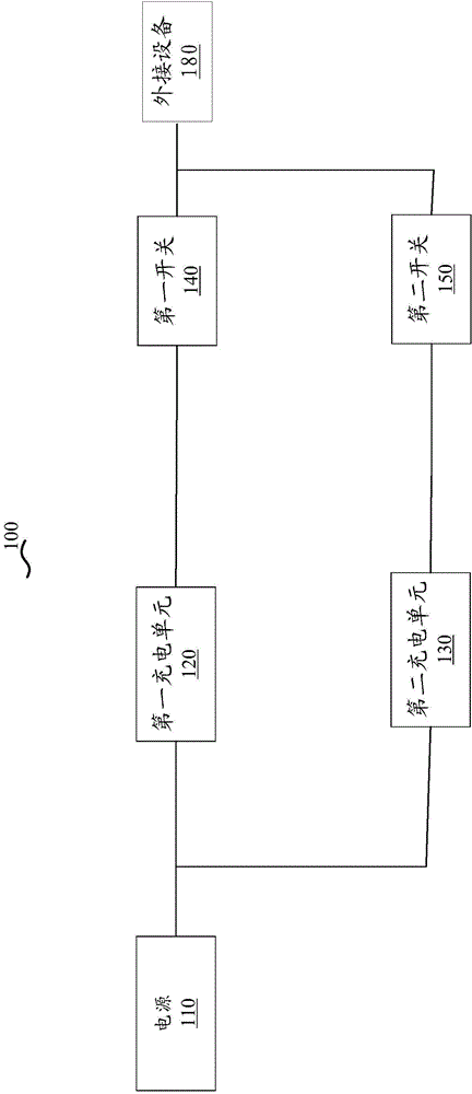
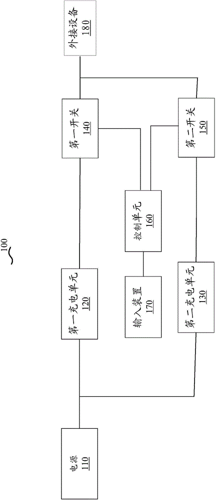
[0022] figure 1 A schematic structural block diagram showing a circuit structure applied to an electr...


PUM


Abstract

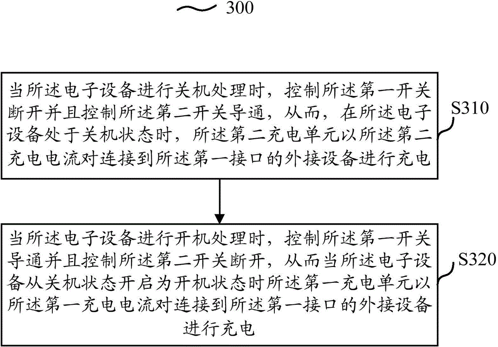
The invention provides electronic equipment, and the electronic equipment comprises a power supply which is used for providing electric energy for the electronic equipment; and a first charging unit which is connected with the power supply and connected with a first interface of the electronic equipment through a first switch. When the first switch is connected, the first charging unit is configured to charge peripheral equipment, connected to the first interface, at a first charging current. The electronic equipment also comprises a second charging unit, and the second charging unit is connected with the power supply and is connected with the first interface of the electronic equipment through a second switch. Moreover, when the second switch is connected, the second charging unit is configured to charge the peripheral equipment, connected to the first interface, at a second charging current. External charging electronic equipment serving as main equipment can carry out charging of equipment during shutdown. Moreover, a user can select quick charging or slow charging. When the user selects the quick charging, the electronic equipment can provide a larger charging current.

Description

technical field [0001] The present invention relates to an electronic device, and more particularly to an electronic device having a circuit structure of charging units with different charging currents. Background technique [0002] At present, electronic devices with USB interfaces such as computers or mobile phones can use the charging function such as OTG (USB On-The-Go) function to charge other electronic devices with USB interfaces, but generally when charging external devices through USB interfaces The charging current is small, so the charging speed is relatively slow and the charging time is relatively long. [0003] Moreover, the externally charged electronic device as the main device must be turned on to charge the external electronic device connected to it through the USB interface. After the shutdown, the external electronic device can no longer be charged through the USB interface. Charging, for example, when a user carries a notebook computer and a mobile phon...

Claims


Application Information

Patent Timeline
Patent Type & Authority Applications(China)
IPC IPC(8): H02J7/00
CPCH02J7/00H02J7/0069Y02B40/00
Inventor 刘一民
Owner LENOVO (BEIJING) LTD
Learn More