Tire/wheel assembly and tread ring

A technology for assemblies and tread rings, applied to tire treads/tread patterns, pneumatic tires, tire parts, etc., can solve problems such as gas reduction, achieve the effects of suppressing deformation, improving driving performance, and suppressing tire blowouts

Active Publication Date: 2015-09-02
THE YOKOHAMA RUBBER CO LTD
View PDF10 Cites 9 Cited by
  • Summary
  • Abstract
  • Description
  • Claims
  • Application Information

AI Technical Summary

Problems solved by technology

Pneumatic tires have the problem of reducing the amount of air and / or nitrogen and other gases filled inside due to punctures, etc.

Method used


Image

  • Tire/wheel assembly and tread ring
  • Tire/wheel assembly and tread ring
  • Tire/wheel assembly and tread ring

Examples


Embodiment approach 1

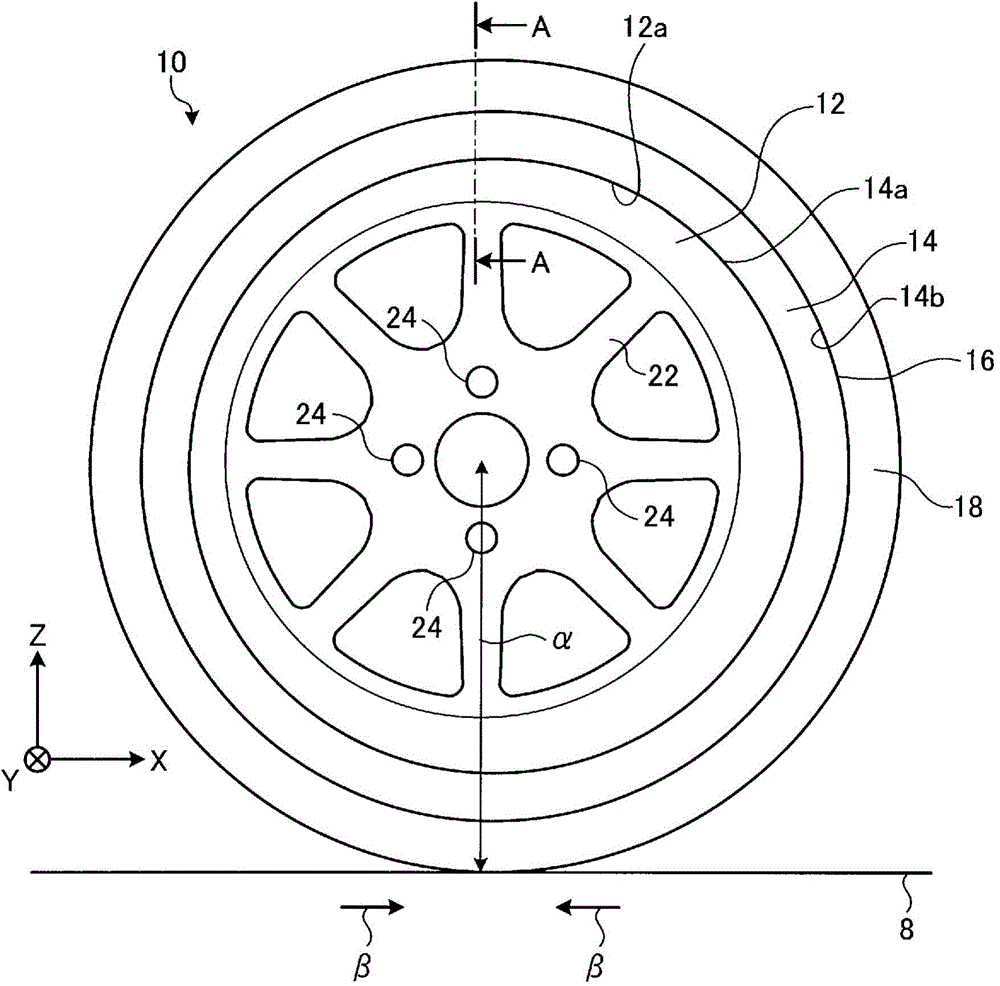
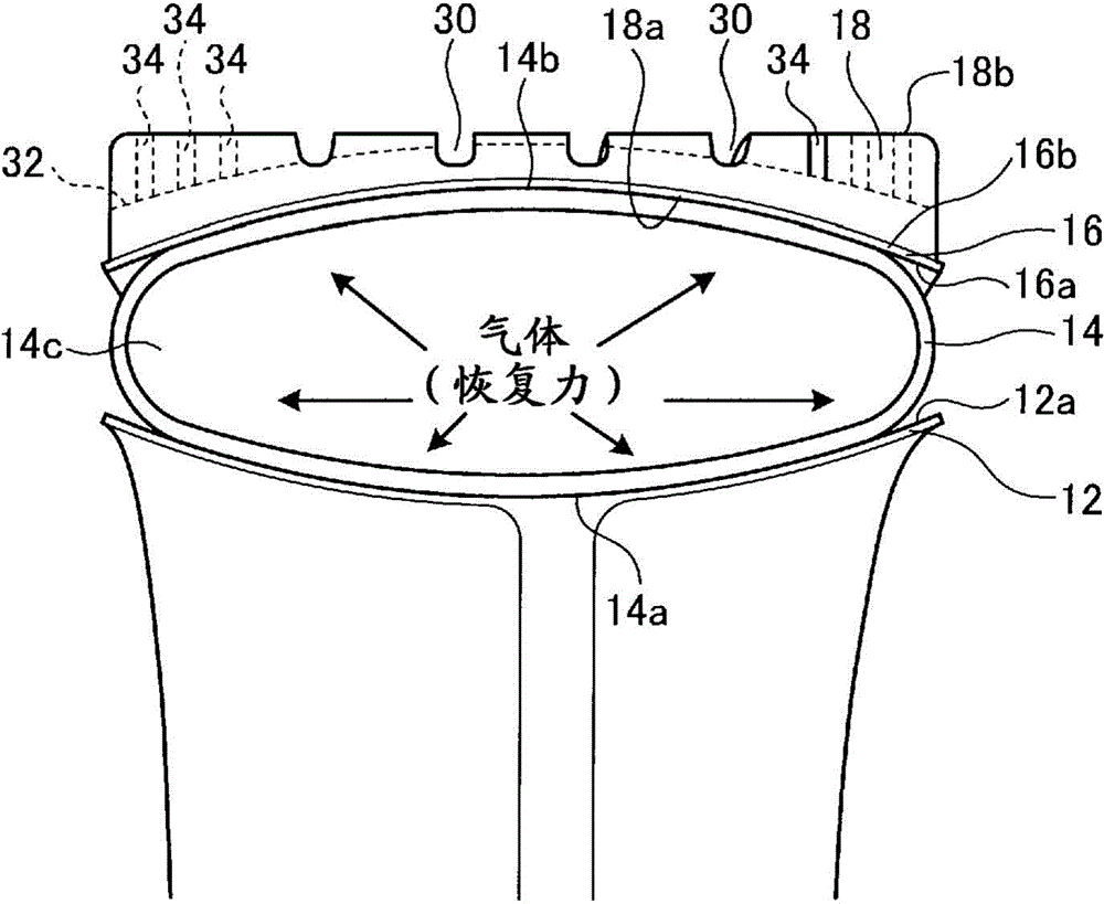
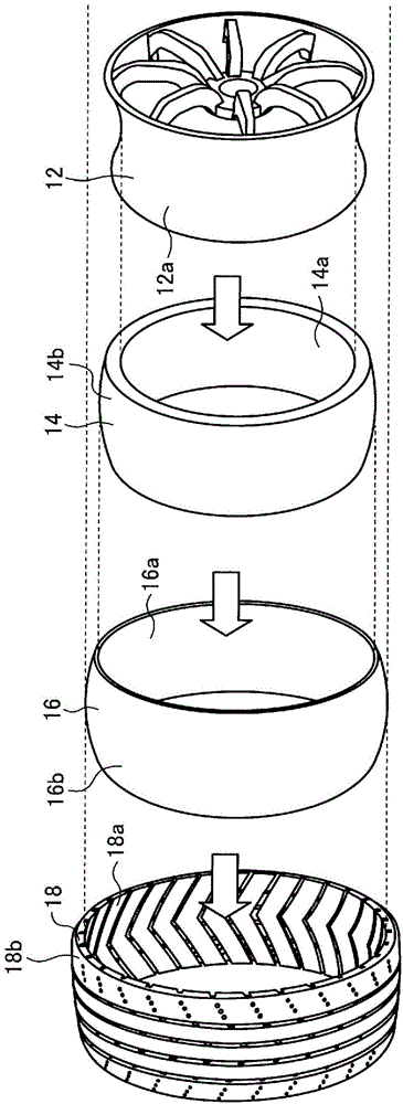
[0052] figure 1 It is a side view showing the schematic structure of an example of the tire / wheel assembly of this embodiment. figure 2 Yes figure 1 The A-A line sectional view in. image 3 Yes figure 1 An exploded perspective view of the tire / wheel assembly shown. Here, the A-A line sectional view is a meridian sectional view of the tire / wheel assembly. The meridian cross section is a cross section when the tire / wheel assembly 10 is cut on a plane parallel to and including the rotation axis of the tire / wheel assembly 10 . In the meridian section, since the tire / wheel assembly 10 is axisymmetric with respect to the rotation axis, the symmetrical side is shown in the present embodiment.

[0053] The tire / wheel assembly 10 rotates around a center axis (Y axis) as a rotation axis. The Y axis is the central axis of the tire / wheel assembly 10 and is the axis of rotation of the tire / wheel assembly 10 . Let the axis perpendicular to the Y-axis, which is the central axis (rota...


PUM


Abstract

The present invention addresses the problem of providing a novel tire / wheel assembly. The tire / wheel assembly has: a wheel coupled to a rotating shaft; an elastic tube arranged on the outside of the wheel in the radial direction and having air filled therein; a rigid protection ring arranged on the outside of the tube in the radial direction, separated from the wheel; and a tread ring arranged on the outside of the protection ring in the radial direction and such that the inner circumferential surface thereof is in contact with the outer circumferential surface of the protection ring.

Description

technical field [0001] The present invention relates to a tire / wheel assembly and a tread ring in which a tire and a wheel are combined. Background technique [0002] Pneumatic tires are widely known as tires generally used for vehicles such as automobiles. The pneumatic tire is attached to the wheel, and the space surrounded by the wheel and the pneumatic tire is filled with air. Pneumatic tires have a problem in that air and / or gas such as nitrogen filled inside decrease due to a blowout or the like. In addition, in recent years, a tire / wheel assembly of a new structure has been studied. For example, as disclosed in Patent Document 1, a non-pneumatic tire in which no gas is filled has been studied. [0003] prior art literature [0004] patent documents [0005] Patent Document 1: Japanese PCT Publication No. 2011-500414 [0006] Patent Document 2: Japanese Patent Application Laid-Open No. 55-8361 [0007] Patent Document 3: Japanese PCT Publication No. 2011-514288 ...

Claims


Application Information

Patent Timeline
Patent Type & Authority Applications(China)
IPC IPC(8): B60C5/00B60C5/08B60C5/24B60C11/00B60C11/02B60C11/04B60C11/13
CPCB60C5/24B60C5/04B60C5/22B60C5/01B60C15/0233B60C11/02B60C15/036B60C11/00B60C11/0323B60C5/18B60C5/20B60C11/032B60C19/125
Inventor 远藤谦一郎松田淳桥村嘉章蔵持泉
Owner THE YOKOHAMA RUBBER CO LTD
Why Eureka
Try Eureka