
Flywheel for electric bicycle mechanical variable speed motor

An electric bicycle, variable speed technology, applied in the field of bicycle parts, can solve the problems of the deceleration mechanism stuck, unable to work, power source stuck, etc., to achieve the effect of compact structure, small size, and insufficient internal space

Active Publication Date: 2017-04-19
严振华
View PDF10 Cites 0 Cited by
  • Summary
  • Abstract
  • Description
  • Claims
  • Application Information

AI Technical Summary

Problems solved by technology

However, in the fourth working state, when the middle fixed ring acts as the active part and moves counterclockwise, the ratchet teeth of the inner and outer rings and the ratchet work at the same time, and the forward and reverse work at the same time will cause the two power sources to be stuck.
If the electric bicycle is pulled out of the garage and needs to be reversed, the inner and outer rings will hook the ratchet teeth, causing the deceleration mechanism to be stuck and unable to work

Method used


Image

  • Flywheel for electric bicycle mechanical variable speed motor
  • Flywheel for electric bicycle mechanical variable speed motor
  • Flywheel for electric bicycle mechanical variable speed motor

Examples


Embodiment 1

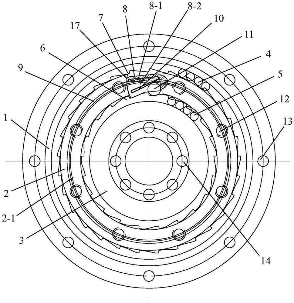
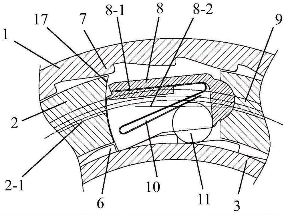
[0025] The preferred solution of this embodiment is that the side surface of the jack piece of the two-way jack control mechanism is provided with a stepped concave platform containing the return spring and the needle roller, the shape of the back spring is an S-shaped leaf spring 10, and the front end of the leaf spring is embedded in the jack In the leaf spring fixing slot 8-1 on the bottom surface of the step concave platform, the lower surface of the leaf spring rear end is in contact with the needle roller 11.

[0026] attached Figure 3-1 As shown, when the needle roller is located on the right side below the jack, the deformation of the leaf spring is small, and the upward jacking force is smaller than the tightening force of the circlip steel wire, and the jack goes down under the action of the tightening force of the circlip steel wire to contact the pawl of the inner ring. .

[0027] Figure 3-2 As shown, when the inner ring rotates counterclockwise, the needle rol...

Embodiment 2

[0030]The preferred version of this embodiment is that the two-way jack control mechanism includes a jack, a ball 18 on the upper side of the jack, a ball 19 on the lower side of the jack, and a ball spring 20. The rear end of the jack is radially provided with a circular hole, and the circle Place the ball on the upper side of the jack, the ball spring and the ball on the lower side of the jack in sequence in the hole.

[0031] Pic 4-1 As shown, when the outer ring rotates counterclockwise and the inner ring rotates clockwise, the friction force between the ball, the outer ring and the inner ring makes the jack piece rotate counterclockwise and contacts the pawl of the inner ring.

[0032] Figure 4-2 and Figure 4-3 As shown, when the outer ring rotates clockwise and the inner ring rotates counterclockwise, the friction force between the ball, the outer ring and the inner ring makes the jack rotate clockwise and contacts the pawl of the outer ring.

Embodiment 3

[0034] The preferred solution of this embodiment is that the two-way jack control mechanism includes a gold plate 8 and a spring hook 21, the shape of the spring hook is Z-shaped, and the front end of the spring hook is embedded in the leaf spring fixing groove on the upper surface of the jack plate. The rear end is in contact with the inner ring ratchet tooth surface.

[0035] Figure 5-1 As shown, the jack piece is lifted upwards under the elastic force of the spring hook and contacts the pawl of the outer ring, the outer ring rotates clockwise, when the inner ring rotates counterclockwise, the outer ring drives the middle fixed ring to rotate clockwise, and the spring hook is inside The ring surface is slippery.

[0036] Figure 5-2 and Figure 5-3 As shown, when the outer ring rotates counterclockwise and the inner ring rotates clockwise, the spring hook hooks the pawl of the inner ring, so that the spring hook drives the jack piece to rotate counterclockwise, and then ...


PUM


Abstract

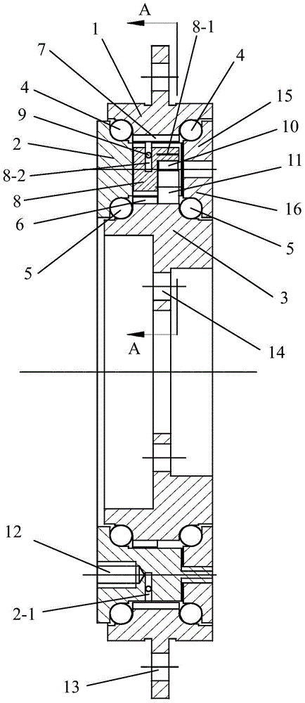
The invention relates to a flywheel for a mechanical speed changing type motor of an electric bicycle. The flywheel comprises an outer ring, an inner ring, balls and jack pieces. The outer ring and the inner ring form the radial two-layer composite structure flywheel comprising a first flywheel structure and a second flywheel structure through a middle fixing ring. The flywheel is characterized in that a rectangular groove is formed in the middle fixing ring, a bi-directional jack control mechanism is installed in the rectangular groove and comprises the jack pieces, reset springs and roller pins, arc protrusions are arranged at the rear end faces of the jack pieces, the arc protrusions are matched with arc grooves in the wall of the inner rectangular groove, clamp spring steel wires are arranged in grooves in the outer circumferences of the jack pieces, and the reset springs and the roller pins are sequentially arranged on the lower surfaces of the jack pieces. The flywheel has the advantages that by means of the bi-directional jack control mechanism, motions in the forward and reverse directions are alternative, and the situation that due to the fact that the jack pieces hook inner and outer ratchet wheel teeth at the same time, a speed reducing mechanism gets stuck.

Description

technical field [0001] The invention belongs to bicycle parts, in particular to a flywheel for a mechanical variable-speed motor of an electric bicycle. Background technique [0002] The flywheel structure currently used in electric bicycles on the market includes an outer ring and an inner ring inside the outer ring, ratchet teeth are arranged on the inner diameter of the outer ring, and at least one concave wedge-shaped groove is provided on the outer diameter of the inner ring. A steel wire (commonly known as a thousand gold spring) and a pawl are housed in the concave wedge-shaped groove. The flywheel only has a single power transmission function. If two powers need to be transmitted to the same structural member, two flywheels can be used, but this method takes up a lot of space. Especially when it is applied inside the electric bicycle motor, the problem is more prominent. The electric bicycle industry urgently needs to solve the problem that the flywheel has only a ...

Claims


Application Information

Patent Timeline
Patent Type & Authority Patents(China)
IPC IPC(8): F16D41/32
Inventor 严振华
Owner 严振华
Learn More