Speed reducer

A technology of reducer and shell, applied in the field of reducer, can solve problems such as injuries and achieve the effect of preventing accidental falling off

Active Publication Date: 2015-09-09
TSUBAKIMOTO CHAIN CO
View PDF8 Cites 2 Cited by
  • Summary
  • Abstract
  • Description
  • Claims
  • Application Information

AI Technical Summary

Problems solved by technology

[0003] If the end of the rotating shaft is exposed from the case, there is a risk of contact with the rotating shaft during rotation and injury, and there is also a risk of accidents due to contact with the rotating shaft

Method used


Image

  • Speed reducer
  • Speed reducer
  • Speed reducer

Examples


Embodiment Construction

[0045] Embodiments of the present invention will be described with reference to FIGS. 1-4. However, the present invention is not limited to this embodiment.

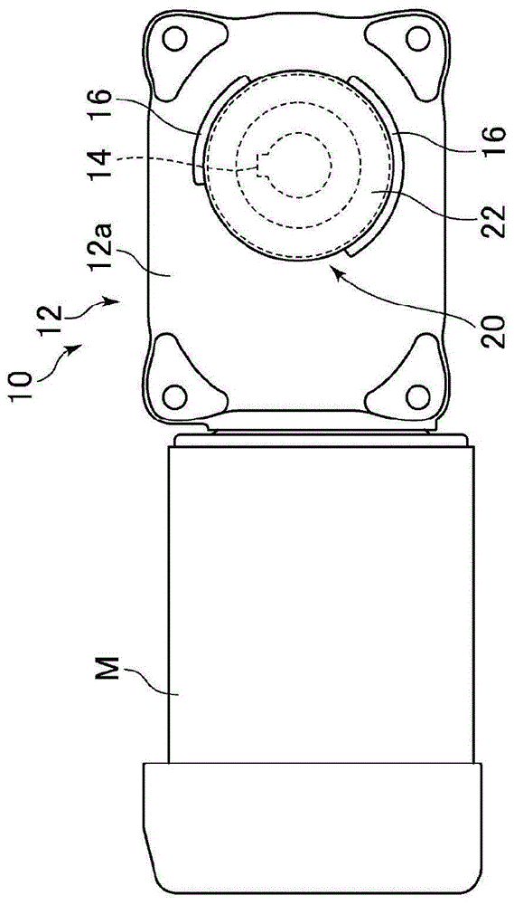
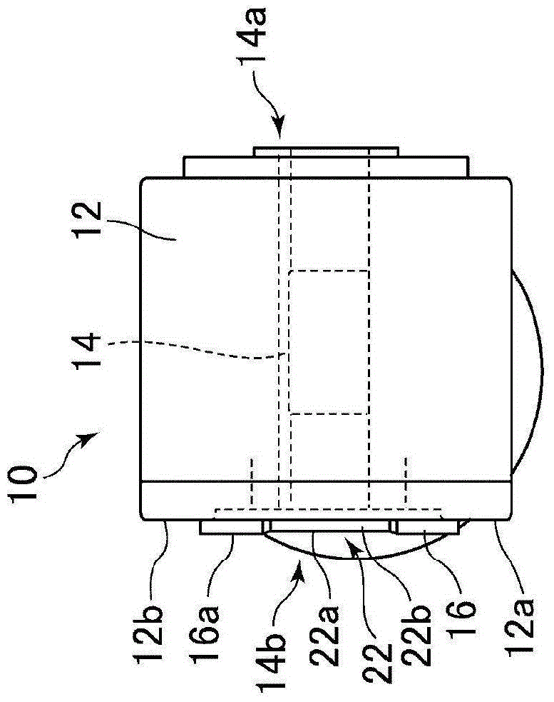
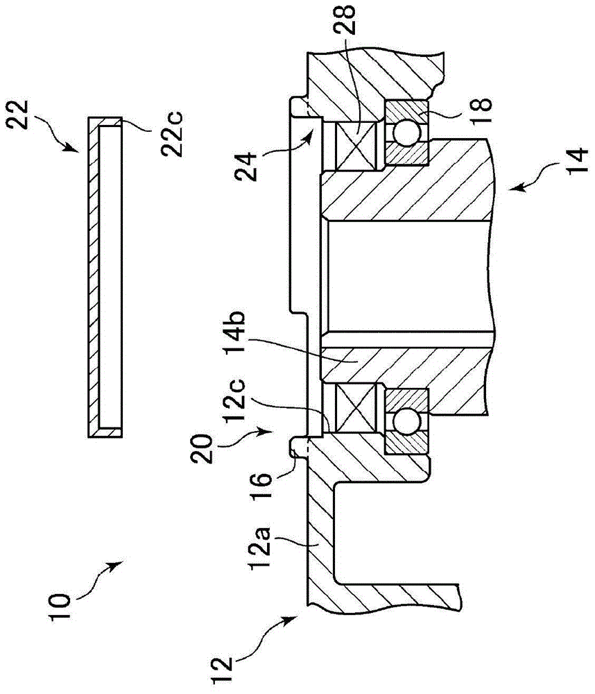
[0046] As shown in FIG. 1( a ), in a speed reducer 10 of the present invention, a housing 12 is connected to a motor M, and the speed reducer 10 has a hollow output shaft 14 for transmitting torque from the motor M. As shown in FIG. As shown in FIG. 1( b ), the hollow output shaft 14 penetrates the housing 12 , and a driven shaft (not shown) is inserted into one end 14 a of the hollow output shaft 14 . On the other hand, the other end 14 b (including the end face) of the hollow output shaft 14 is located inside the housing 12 and exposed from the housing 12 . As shown in FIG. 1( a ), for the housing 12 , a circular opening 20 coaxial with the hollow output shaft 14 is provided on the wall 12 a on the side where the end 14 b of the hollow output shaft 14 is exposed. In the circumferential direction of the edge of the op...


PUM


Abstract

The invention provides a speed reducer which can simply assemble and unassemble a shaft end cover, in which the shaft end cover can not accidently fall off, and the manufacture cost is relative low. The speed reducer (10) is provided with a round opening part (20) coaxial with a hollow output shaft (14) and having a radial direction size more than an external diameter of an oil seal (28) at a wall part (12a) of the exposure side of the end (14b) of the hollow output shaft (14) of a housing (12). Non-continuous projection strip parts (16) projecting from an external wall surface (12b) of the wall part (12a) are arranged in the peripheral direction at the edge of the opening part (20). A shaft end cover (22) is embedded in the opening part (20). The surface (22a) of the shaft end cover (22) is arranged between end faces (16a) of the projection strip parts (16) and external wall faces (12b) of the wall part (12a), thus the shaft end cover (22) can be simply assembled and unassembled, the shaft end cover (22) won't accidently fall off, and the manufacture cost is relative low.

Description

technical field [0001] The present invention relates to a speed reducer in which an end of a rotating shaft is exposed from a housing, and a cover for covering the end (hereinafter simply referred to as "shaft end cover") is mounted on the end. The exposed side of the housing wall. Background technique [0002] Among the speed reducers, there is a speed reducer in which an end portion of a rotating shaft is exposed from a case. For example, reducers of the type with a hollow final output shaft passing through the housing fall into this category. In addition, a speed reducer in which a hole is provided at a position corresponding to the end of the rotating shaft of the housing for convenience of maintenance or the like also belongs to this category. [0003] When the end portion of the rotating shaft is exposed from the housing, there is a risk of contact with the rotating shaft during rotation and injury, and there is also a risk of accidents due to contact with the rotati...

Claims


Application Information

Patent Timeline
Patent Type & Authority Applications(China)
IPC IPC(8): F16H57/031F16H57/029
CPCF16H57/029F16H57/031
Inventor 木村宗博坪田润一椎野里司
Owner TSUBAKIMOTO CHAIN CO
Why Eureka
Try Eureka