A connection structure between multi-core photonic crystal fiber and laser light source

A technology of photonic crystal fiber and connection structure, applied in the direction of multi-core fiber, cladding fiber, optical waveguide light guide, etc. Large transmission data capacity, easy splicing, and the effect of reducing the number of optical fibers

Active Publication Date: 2018-07-17
深圳市同昇光电有限公司
View PDF9 Cites 0 Cited by
  • Summary
  • Abstract
  • Description
  • Claims
  • Application Information

AI Technical Summary

Problems solved by technology

Among them, the common method of reducing crosstalk in solid multi-core optical fiber is to increase the core spacing, but this also greatly limits the number of cores in multi-core optical fiber, thereby reducing the communication capacity, and will also increase the pump light energy required by the communication system.

Method used


Image

  • A connection structure between multi-core photonic crystal fiber and laser light source
  • A connection structure between multi-core photonic crystal fiber and laser light source
  • A connection structure between multi-core photonic crystal fiber and laser light source

Examples


Embodiment 1

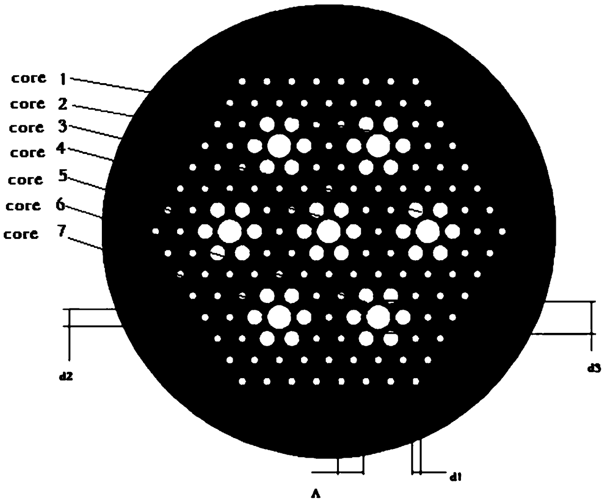
[0030] Such as figure 1 As shown, the core of the small-pitch multimode seven-core fiber is made of high-purity silica + F-doped low-refractive index glass, and each core is surrounded by 6 air claddings with a large duty cycle. All seven structures including the above-mentioned core and air cladding form a seven-core optical fiber in a centrosymmetric manner. The air holes are arranged in a positive hexamorphic array. The diameter of the small hole of the optical fiber is d1, the diameter of the six air holes with a large duty cycle is d2, the diameter of the fiber core is d3, and the distance between the small holes of the optical fiber is Λ. The range of d1 is 2.5-2.9um, the range of d2 is 5.5-6.4um, the range of d3 is 13-15um, and the range of Λ is 6.4-6.8um. From the point of view of the fiber core spacing, the distance between any two adjacent fiber cores is 25.6-28um. This design of fiber core spacing can correspond to the LED chip-level array layout, because corresp...

Embodiment 2

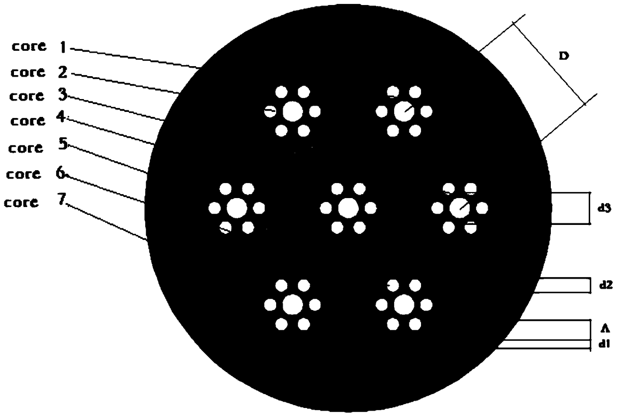
[0035] Such as image 3 As shown, the difference from Example 1 is that the range of Λ is 6.0-6.3um; from the point of view of the fiber core spacing, the distance between any two adjacent fiber cores is within the range of 36-37.8um. ​​This design can be applied to Splicing VCSEL arrays or splicing LED arrays in the later stage. Because corresponding to the application of device-level light sources, it is also easy to realize a light source device array with a pitch in the range of 36-37.8um. This approach is flexible, convenient and more attractive to small integrators.

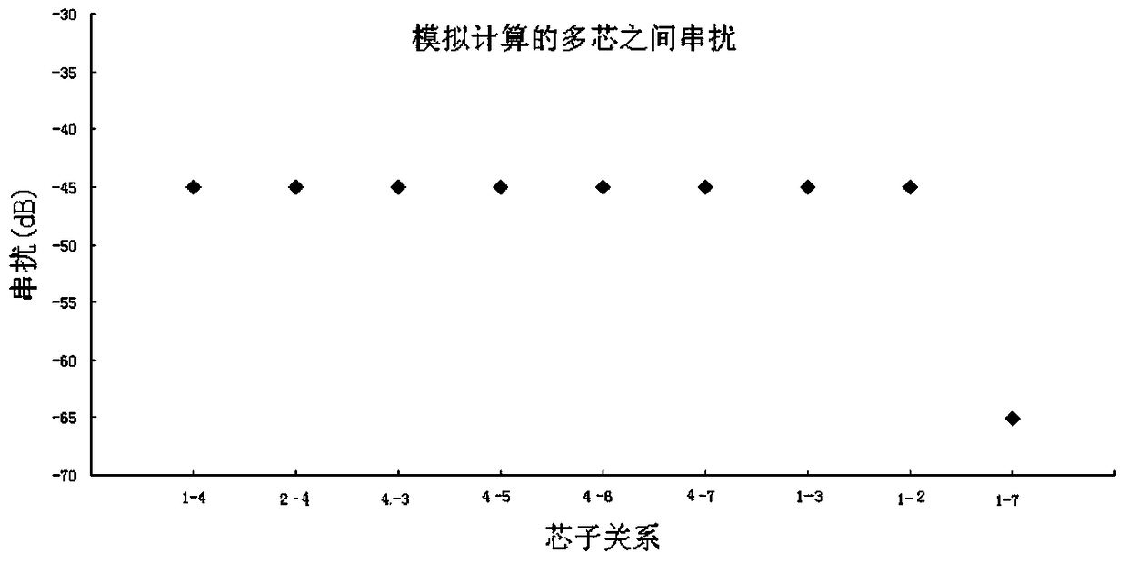
[0036] Such as Figure 4 As shown, it can be seen from the simulation calculation that the maximum crosstalk between the cores of the large-pitch multimode multi-core photonic crystal fiber is -60dB, and the mutual interference between multiple cores can be ignored in the design of the communication system.

Embodiment 3

[0038] Such as Figure 5 As shown, the hole diameter of the single-mode seven-core fiber is d1, the diameter of the six air holes with a large duty cycle is d2, the diameter of the fiber core is d3, and the hole spacing of the fiber is Λ. The range of d1 is 2.5-2.9um, the range of d2 is 5.5-6.4um, and the range of d3 is 9-10um. The range of Λ is 6.6-7.2um. From the point of view of the fiber core spacing, the distance between any two fiber cores is 41.6-42um. Each core of this 7-core single-mode fiber has a mode leakage channel, so it is very easy to form a single-mode transmission at any wavelength, which meets the requirements of high-speed, large-bandwidth short-distance data communication. Since the distance between the two cores exceeds 40um, the attenuation of high-order modes in the fiber mainly comes from material absorption and interface loss, so it is difficult for the energy of one core to propagate to the other. This design guarantees the single-mode transmissio...


PUM


Abstract

The invention discloses a connection structure between a multi-core photonic crystal fiber and a laser light source. Medium holes which are periodically arranged are arranged in a radial two-dimension direction of the multi-core photonic crystal fiber. The medium holes form a medium hole array, and the diameter of each medium hole is d1. A plurality of non-adjacent medium holes areabsent in the medium hole array, thereby forming N fiber cores, and diameters of medium holes around each fiber core are d2, wherein d2 is larger than d1 (d2>d1). The laser light source has a light source array which is formed by N light sources. The N light sources and the N fiber cores are in one-to-one alignment connection. A gap between two adjacent fiber cores is equal to a gap between two corresponding adjacent light sources. The connection structure provided by the invention can be applied to short distance communication of data rooms and the like, reduces the number of fibers in a machine room, and can be applied to the layout of a chip-level array, and an LED array or a VCSEL array which is integrated by later joint. With the connection structure, multiple single mode fibers can be jointed, and reconstruction of fibers in the data room is enabled to be very convenient and to have obvious effects.

Description

technical field [0001] The invention relates to the field of design and manufacture of photonic crystal fibers, in particular to a connection structure between a multi-core photonic crystal fiber and a laser light source. Background technique [0002] In recent years, with the expansion of Internet data throughput represented by mobile Internet applications, the capacity and speed of data centers have been continuously improved. The traditional short-distance communication is composed of LED+multimode optical fiber, which is low in cost and easy in wiring, and is very successful in the application of ordinary data centers. At present, with the rapid expansion of data center business, the common LED + multimode fiber solution has been difficult to meet the application requirements. Therefore, the large-scale application of VCSEL laser + multimode fiber has become a reality. The use of VCSEL lasers has two major advantages, one is the improvement of the transmission rate; th...

Claims


Application Information

Patent Timeline
Patent Type & Authority Patents(China)
IPC IPC(8): G02B6/02G02B6/42
CPCG02B6/02042G02B6/02333G02B6/02338G02B6/02347G02B6/4296
Inventor 成煜翟真德
Owner 深圳市同昇光电有限公司
Why Eureka
Try Eureka