Eureka AIR delivers breakthrough ideas for toughest innovation challenges, trusted by R&D personnel around the world.

Combination structure of electric connection between control unit and power supply unit

A technology of power supply unit and control unit, which is applied to the parts, connections, fixed/insulated contact components of the connection device, etc., which can solve the problems of helpless insulation and waterproof effect, excessive manufacturing and processing, and easy short circuit of the conductive sheet.

Inactive Publication Date: 2015-09-09
HIWIN MIKROSYST
View PDF5 Cites 2 Cited by
  • Summary
  • Abstract
  • Description
  • Claims
  • Application Information

AI Technical Summary

Problems solved by technology

[0005] A specific known technology is as figure 1 As shown, when the conductive sheet 1 is used as the electrical connection between the power supply unit 2 and the control unit 3, the connection between the power supply unit 2 and the control unit 3 is achieved by using an annular slot 4 and an annular wall 5 Embedded with each other, so that the power supply unit 2 and the control unit 3 are connected and fixed in series, so that the conductive sheets 1 of the power supply unit 2 and the control unit 3 can be attached to each other, so that the The combined state of the power supply unit 2 and the control unit 3 is electrically connected to each other. In these known technologies, there is a risk of short circuit caused by water seepage because the gap around the conductive sheet 1 is too large. At the same time, the conductive sheet is too large. The volume is also derived from easy short circuit and there is a need for higher insulation protection
[0006] Another specific known technology is to electrically connect the male end plug and the female end socket to the power supply unit and the control unit respectively, and then lock them on the housings of the power supply unit and the control unit respectively. These technical contents Due to the lack of proper insulation and positioning technology for the male-end plug and the female-end socket, the processing method of locking and assembling the parts is adopted, which not only increases the tediousness and inconvenience of manufacturing and processing, but also does not help to achieve the effect of insulation and waterproofing

Method used


Image

  • Combination structure of electric connection between control unit and power supply unit
  • Combination structure of electric connection between control unit and power supply unit
  • Combination structure of electric connection between control unit and power supply unit

Examples


Embodiment Construction

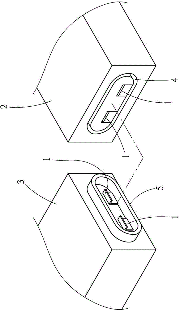
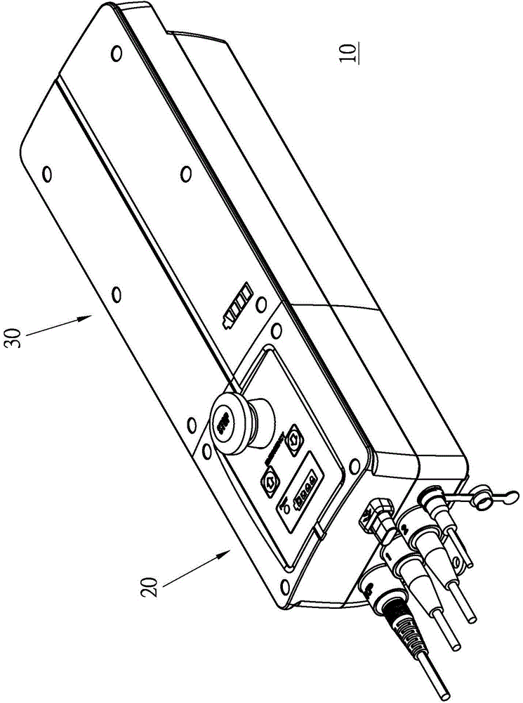
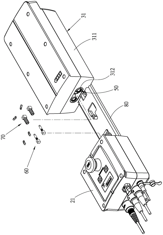
[0029] First, see Figure 2 to Figure 6 As shown, the combination structure 10 disclosed in a preferred embodiment of the present invention for the electrical connection between the control unit and the power supply unit mainly includes a first unit 20, a second unit 30, a first combination part 40, A second combining portion 50 , a first electrical connection portion 60 and a second electrical connection portion 70 .

[0030] The first unit 20 and the second unit 30 can be the control unit used to control the equipment as disclosed in the known technology and the power supply unit used to provide the control unit with electric energy, but they are used to achieve the control of the equipment and through the storage battery Providing electric energy and other technical content is not the technical feature of the present invention, so it will not be redundant here, but what should be explained is that the first unit 20 has a hollow first shell body 21, and the The second unit ...


PUM


Abstract

The invention provides a combination structure of electric connection between a control unit and a power supply unit. The combination structure comprises a first unit, a second unit, a first combination portion, a second combination portion, a first electric connection portion and a second electric connection portion. In the combination structure, one portion of each of a majority of electric connection terminals is wrapped in corresponding one of housings of different units respectively, and is arranged in corresponding one of clamping structures for being mutually embedded of the housings of the different units simultaneously, so that when the housings of the different units are mutually clamped and combined, the electric connection terminals are allowed to be electrically connected.

Description

technical field [0001] The present invention relates to equipment control technology, in particular to a combined structure for electrical connection between a control unit and a power supply unit. Background technique [0002] As far as the controller is generally used to control equipment, the power required by the control unit during operation is usually supplied by a power supply unit such as a battery that is independent of the controlled equipment, so that the user can The control unit controls the action of the device with control signals in a wired or wireless manner. [0003] Due to the limited capacity of independent power supply units such as batteries, in order to facilitate the replacement of the power supply unit, the electrical connection technology between the power supply unit and the control unit usually adopts an easy-to-plug connection technology such as concave-convex complementary plugging or conductive sheet bonding. The method makes the disassembly a...

Claims


Application Information

Patent Timeline
IPC IPC(8): H01R13/40H01R13/502H01R13/639
CPCH01R13/40H01R13/502H01R13/639H01R13/6395
Inventor 廖丽芬许祯
Owner HIWIN MIKROSYST
Why Eureka
Eureka Blog
Learn More