Pump unit

A technology for pump units and electronic devices, applied in the direction of pumps, pump devices, electromechanical devices, etc., can solve the problems of easy installation, high cost, cable sealing, etc.

Active Publication Date: 2015-09-09
GRUNDFOS HLDG
View PDF8 Cites 3 Cited by
  • Summary
  • Abstract
  • Description
  • Claims
  • Application Information

AI Technical Summary

Problems solved by technology

This in turn leads to higher costs and error-prone installation
Another problem is the need to seal the cables in the cable channels

Method used


Image

  • Pump unit
  • Pump unit
  • Pump unit

Examples


Embodiment Construction

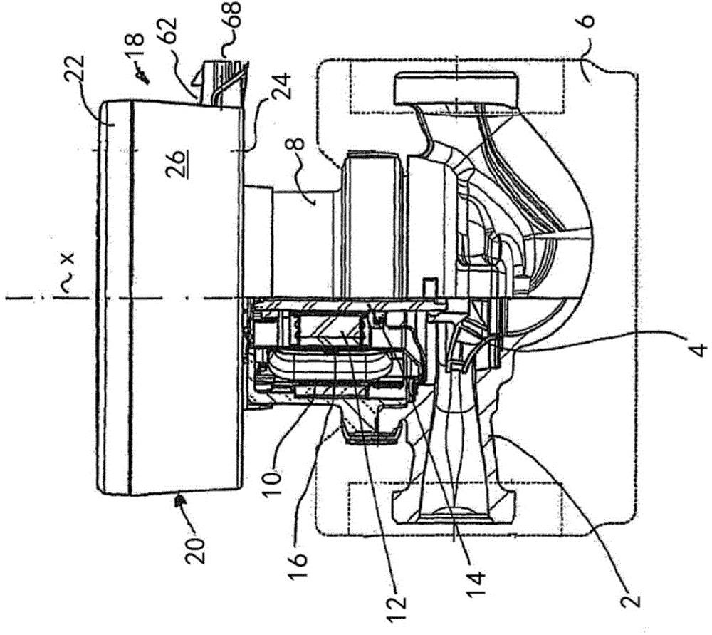
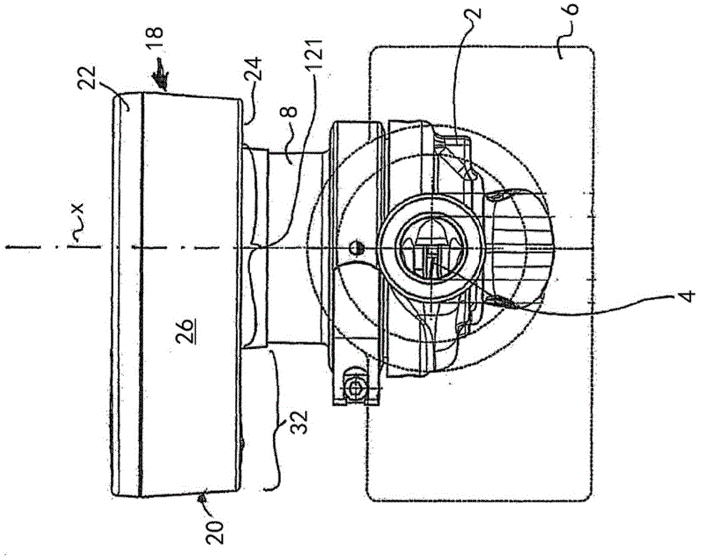
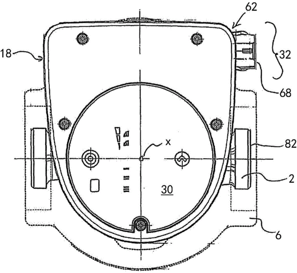
[0054] Refer below Figure 1-Figure 13 The first preferred embodiment of the present invention will be described. here, Figure 1-Figure 3 , Picture 12 with Figure 13 A general diagram of the pump unit according to this preferred embodiment is shown. The pump unit has a pump housing 2 in a known manner, in which an impeller 4 is arranged. The pump unit is designed as a centrifugal pump unit. In the embodiment shown here, the pump housing 2 is surrounded by the isolation element 6. The pump housing 2 is connected to a motor housing or a stator housing 8, and the motor housing or the stator housing is connected to the pump housing 2 in the direction of the longitudinal axis or the rotation axis X in the axial direction. An electric drive motor is provided in the stator housing 8, which has, in particular, a stator 10 and a rotor 12 rotatable in the stator. Preferably, the rotor 12 is configured as a permanent magnet rotor. The rotor 12 is connected to the impeller 4 in a ro...


PUM


Abstract

The assembly has a stator connecting element (48) and a network connecting element (62) formed as molded plastic parts, and arranged on or in an electronics housing. The connecting elements include electrical plug-in connectors (52, 66) that are connected to a corresponding electrical plug-in coupling on a printed circuit board. The connecting elements include other electrical plug-in connectors (54, 68), which are connected to the former electrical plug-in connectors via cast conductor tracks (56) and serves as an electrical connection of a component that is located outside of the housing.

Description

Technical field [0001] The invention relates to a pump unit having the characteristics described in the preamble of claim 1. Background technique [0002] A pump unit, such as a heating circulating pump unit, usually constitutes a structural unit, which includes an electric drive motor and a pump, such as a centrifugal pump. The electric drive motor is arranged in a motor housing or a stator housing, and the motor housing or the stator housing is connected with the actual pump, that is, the pump housing. The electrical and electronic devices required to control or regulate the electric drive motor are usually arranged in a junction box or an electronic device housing, and the electronic device housing is connected to the stator housing. [0003] In order to connect the coil in the stator housing to the power connection wire, and to connect other electronic devices as required, it is necessary to provide plug contacts or cable channels on the electronic device housing. For this re...

Claims


Application Information

Patent Timeline
Patent Type & Authority Applications(China)
IPC IPC(8): H02K5/22H02K11/00
CPCH02K11/0073H02K5/225H02K11/30H02K11/33H02K5/22F04D25/06H02K11/0094
Inventor M·E·奥尔森C·舒尔特
Owner GRUNDFOS HLDG
Why Eureka
Try Eureka