The installation structure of Rubik's cube center block

A technology of installation structure and center block, which is applied in the Rubik's Cube field, can solve problems such as difficult adjustment, uneven tightness of the Rubik's Cube, and inaccurate installation position, and achieve the effects of high assembly accuracy, consistent tightness, and improved stability

Active Publication Date: 2018-05-01
江淦源
View PDF5 Cites 5 Cited by
  • Summary
  • Abstract
  • Description
  • Claims
  • Application Information

AI Technical Summary

Problems solved by technology

[0003] But the formation of the axis structure of existing Rubik's Cube is to offer threaded hole directly on the axis usually, in the threaded hole, the screw that is connected with spring and center block is threaded, finally just can form the axis structure of a Rubik's Cube, and because of screw It is tightened by hand or electric tools, and the installation position is not accurate enough, which will affect the assembly of other small cubes; at the same time, this installation method may make the center block deviate from the center of the axis, resulting in uneven rotation of the Rubik's Cube
At the same time, the different strength of turning the screw will also cause the radial position of the center block of each surface to be inconsistent, so that the elasticity of each surface of the Rubik's Cube is different.
[0004] In addition, in order to prevent the Rubik's Cube from falling apart during the rotation, a spring is usually provided in the center block to provide a pre-tightening force, but the screw hole used to adjust the compression of the spring is passed through the traditional nut. The tightness of each side of the Rubik’s Cube can only be controlled by the assembler, and the tightness of each side cannot be completely guaranteed, and the spring will also deflect during the adjustment process, causing the spring to be crooked and difficult to adjust

Method used


Image

  • The installation structure of Rubik's cube center block
  • The installation structure of Rubik's cube center block
  • The installation structure of Rubik's cube center block

Examples


Embodiment Construction

[0017] Below, in conjunction with accompanying drawing and specific embodiment, the present invention is described further:

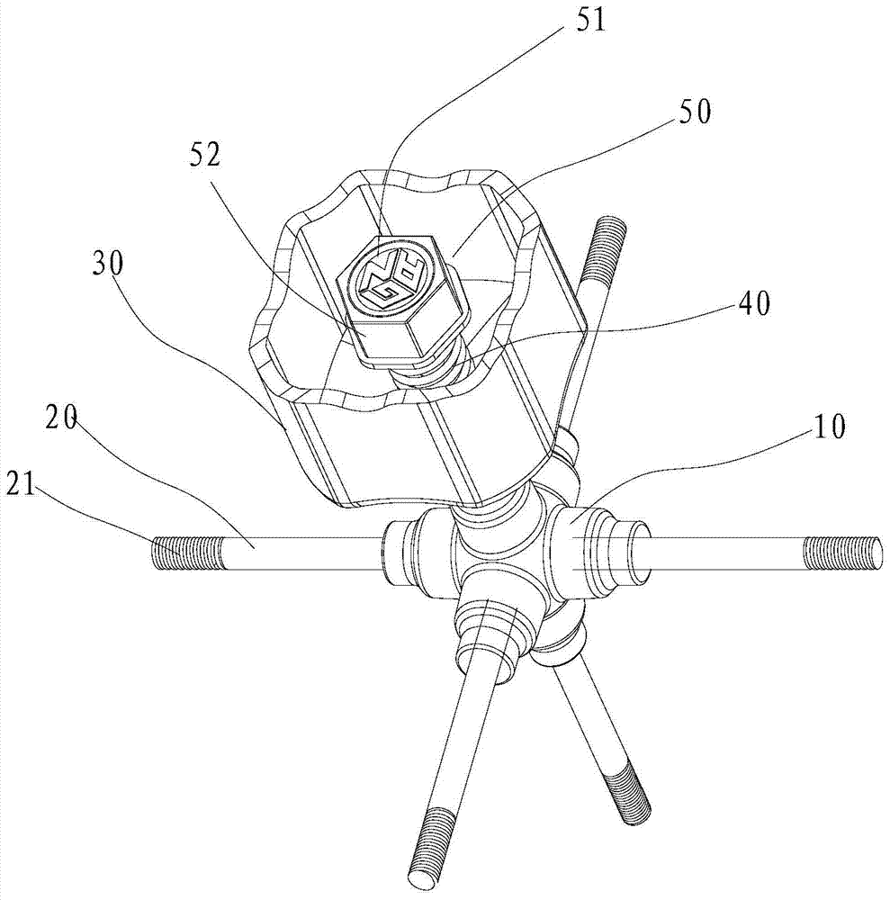
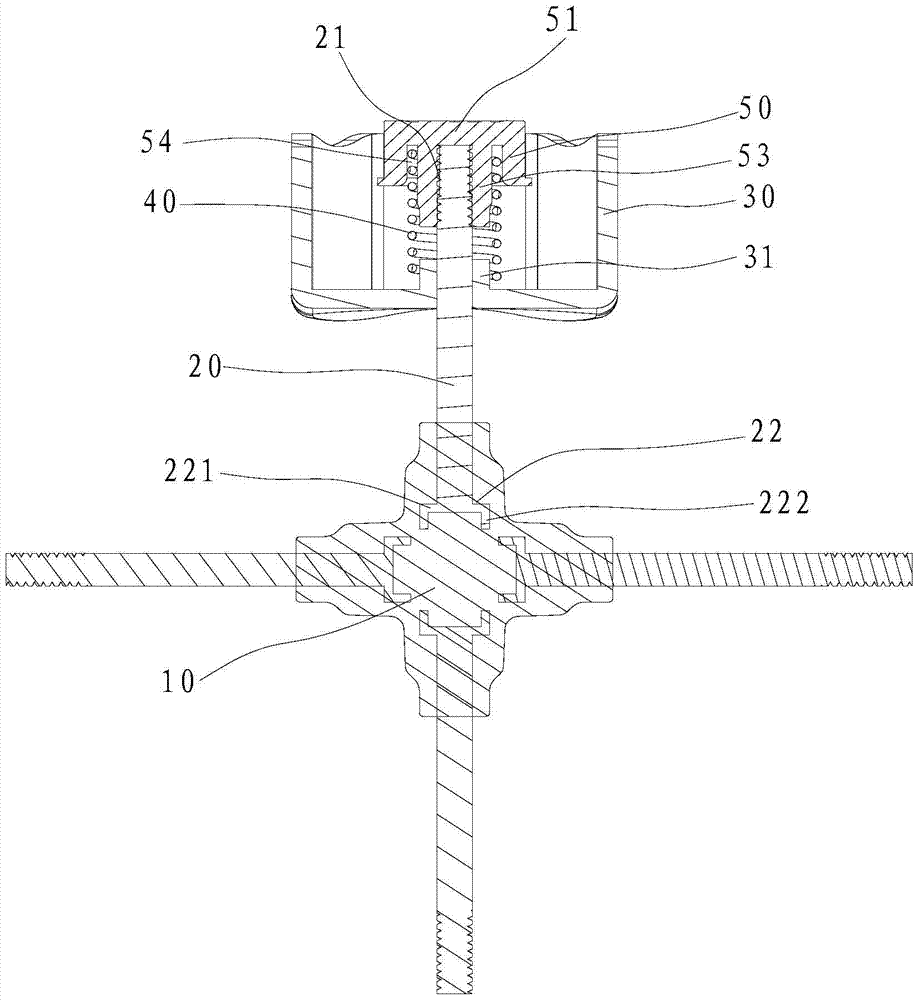
[0018] Such as figure 1 , 2 as well as image 3 The mounting structure of the shown Rubik's Cube center block, in this embodiment, takes the traditional third-order Rubik's Cube as an example, including the axis 10, the connecting rod 20, the center block 30 and the elastic member 40, so that one end of the connecting rod 20 is connected to the In the center block 30, the other end of the connecting rod 20 is provided with an embedding part 22 embedded in the shaft center. The embedding part 22 includes an extension part 221 and an insertion part 222. Specifically, the extension part 221 is located at the lower end of the connecting rod 20 and Extending outward along the radial direction of the connecting rod 20, and the insertion part 222 is formed by extending downward from the edge of the extending part 221. This structure increases the contact are...


PUM


Abstract

An installation structure for magic cube center blocks comprises a shaft center, the center blocks, connecting rods and elastic parts, one end of each connecting rod is provided with an embedded portion which is embedded in the shaft center, and each embedded portion comprises an extending portion and an inserting portion; the other end of each connecting rod is connected into the corresponding center block in a penetrating mode, an outer thread is formed in the outer surface of the portion, connected into the corresponding center block in a penetrating mode, of each connecting rod, an adjusting block is arranged on the portion, connected into the corresponding center block in a penetrating mode, of each connecting rod, and each adjusting block comprises a top wall, side walls located on the periphery of the lower surface of the top wall and a first sleeving installation portion which extends downwards from the lower surface of the top wall and is installed on the outer surface of the corresponding connecting rod in a sleeving mode; the inner surface of each sleeving installation portion is provided with an inner thread matched with the corresponding outer thread, and an installation groove is formed between the outer surface of each sleeving installation portion and the corresponding side walls; one end of each elastic part is arranged in the corresponding installation groove and abuts against the lower surface of the corresponding top wall, and the other end of each elastic part abuts against the inner side end wall of the corresponding center block. According to the installation structure for the magic cube center blocks, the center shaft structure is stable, the degrees of tightness of all faces of a magic tube are consistent, and the assembly is convenient.

Description

technical field [0001] The invention relates to the technical field of Rubik's cube, in particular to an installation structure of a Rubik's cube center block. Background technique [0002] The existing Rubik's Cube is composed of multiple unit blocks and multi-dimensional connecting shafts. Taking the traditional third-order Rubik's Cube as an example, its main body is a cube structure, including 26 small squares and a three-dimensional connecting shaft. The small squares include six A central block located at the center of each face of the Rubik's Cube, eight corner blocks located at the end corners of the Rubik's Cube, and twelve edge blocks respectively located between adjacent two corner blocks, so that each face of the Rubik's Cube is nine Each layer of the Rubik's Cube can rotate freely based on the rotation characteristics of the three-dimensional shaft. When assembling the Rubik's Cube, connect the six central blocks to the ends of the three-dimensional connecting ...

Claims


Application Information

Patent Timeline
Patent Type & Authority Patents(China)
IPC IPC(8): A63F9/08
Inventor 江淦源
Owner 江淦源
Why Eureka
Try Eureka