Supercharge Your Innovation With Domain-Expert AI Agents!

A circular saw with a moving mechanism

A mobile unit, sawing machine technology, applied in metal sawing equipment, sawing machine devices, manufacturing tools, etc., can solve the problems of lengthening the sliding bar 16, affecting the sawing accuracy, increasing the thickness of the structure, etc., to improve the stability. Effect

Active Publication Date: 2015-09-16
REXON IND CORP LTD
View PDF7 Cites 2 Cited by
  • Summary
  • Abstract
  • Description
  • Claims
  • Application Information

AI Technical Summary

Problems solved by technology

[0007] 1. When the saw arm 14 slides through the slide bar frame 15 through the slide bar 16 in the slide seat 17, and performs sawing action at a position away from the slide bar frame 15, due to the sliding The rods 16 are arranged at horizontal intervals, so that the slide seat 17 produces a yaw moment relative to the slide bar frame 15 due to the load of the saw arm 14 and the slide bar 16, which easily causes the saw arm 14 to shake up and down, affecting the saw arm 14. In addition, because the stability of the saw arm 14 is not good, it is easy to generate large vibration during sawing and affect the service life of the machine
[0008] 2. Since the slide seat 17 is supported on the base 12 by the slide bar frame 15, in order to maintain structural strength to support the weight of the saw arm 14 and the slide bar 16, the slide bar frame 15 is used for the slide bar frame 15. The structural thickness of the rod 16 socket is bound to increase, and at the same time in order to maintain a certain specification of the sawing stroke, the structural length of the sliding rod frame 15 for the sliding rod 16 socketing is bound to increase, so the length of the sliding rod 16 must also be lengthened , increasing the overall cost of
[0009] 3. Since the saw arm 14 is arranged on the front end of the sliding seat 17, when it is desired to perform sawing work, the rear side of the base 12 needs to reserve a space for the sliding of the sliding seat 17 to facilitate operation, and a relatively generous working space is required. When storing or transporting, a large space is also required, so the overall volume of the existing sawing machine is huge and has the disadvantage of occupying space

Method used


Image

  • A circular saw with a moving mechanism
  • A circular saw with a moving mechanism
  • A circular saw with a moving mechanism

Examples


Embodiment Construction

[0031] Below in conjunction with accompanying drawing and embodiment the present invention is described in detail:

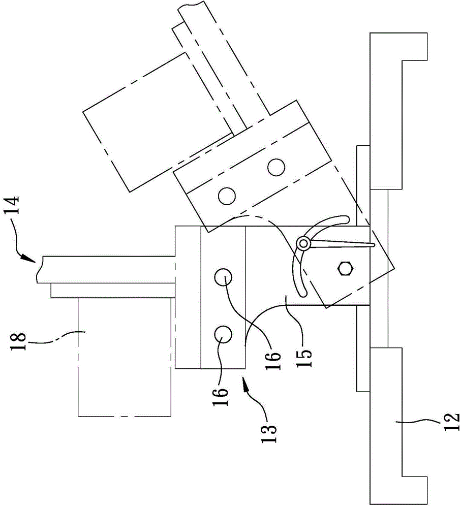
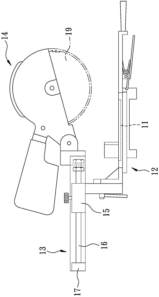
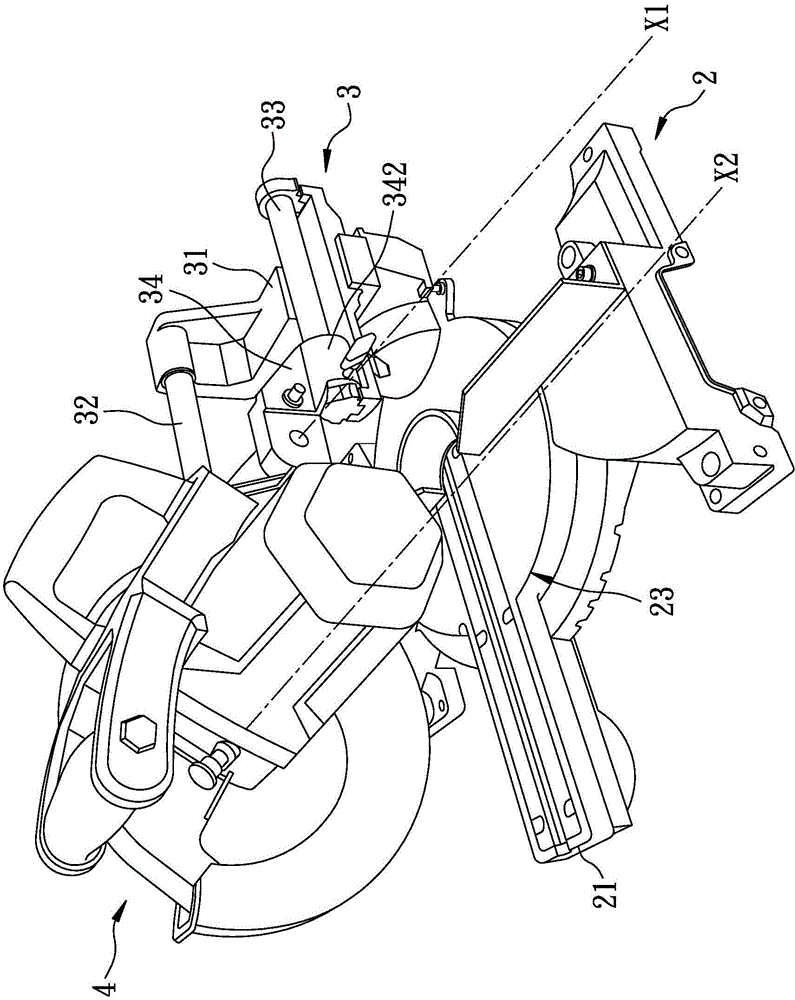
[0032] refer to image 3 , Figure 4 and Figure 8 , The preferred embodiment of the sawing machine with sliding unit of the present invention includes a carrier unit 2 , a moving unit 3 and a sawing unit 4 .

[0033] The carrier unit 2 includes a worktable 23 with a front side 21 and a rear side 22 opposite to each other, and a horizontal first plane F1 extending from the rear side 22 to the front side 21 .

[0034] The mobile unit 3 is located above the workbench 23, and includes a support base 31 arranged on the workbench 23, a first slide bar 32 and a second slide bar 33 respectively arranged in parallel and spaced on the support base 31, and A slide seat 34 is disposed on the first slide bar 32 and the second slide bar 33 .

[0035] In this embodiment, the first slide bar 32 is fixed on the support base 31 at the end far away from the sawing unit 4 (see...


PUM


Abstract

The invention discloses a saw cutting machine provided with a moving unit comprising a carrier unit, a moving unit, and a saw cutting unit. The carrier unit comprises a working bench provided with a front side and a rear side, which are opposite to each other; and a first plane, which is horizontally arranged, and is extended from the rear side to the front side. The moving unit is disposed above the working bench, and comprises a supporting seat disposed on the working bench; a first sliding rod and a second sliding rod, which are parallely arranged on the supporting seat; a sliding seat disposed on the first sliding rod and the second sliding rod. A second plane can be defined by a self-axis of the first sliding rod and a self-axis of the second sliding rod, and an included angle between the second plane and the first plane is larger than 0degree and the smaller than 90degrees. The saw cutting unit is pivoted to the sliding seat, and can move linearly with respect to the working bench along the horizontal direction.

Description

[0001] This application is a divisional application, the application number of the parent application: 2012101528148, the application date of the parent application: May 14, 2012, the name of the parent application: a sawing machine with a mobile unit. 【Technical field】 [0002] The invention relates to a sawing machine, in particular to a sawing machine with a mobile unit. 【Background technique】 [0003] refer to figure 1 and figure 2 , an existing sawing machine with a displaceable saw arm (Taiwan No. 152478 patent case), has a base 12 with a saw groove 11, a shift group 13 pivotally arranged on the base 12, And a saw arm 14 pivotally arranged on the shifting group 13 . [0004] The shifting group 13 has a slide bar frame 15 arranged on the base 12, two slide bars 16 parallel to the saw groove 11 and movable and horizontally spaced through the slide bar frame 15, and a The slide bar 16 is fixed and the slide seat 17 for the saw arm 14 is pivotally set. [0005] The sa...

Claims


Application Information

Patent Timeline
Patent Type & Authority Applications(China)
IPC IPC(8): B23D47/02
Inventor 邱成宏
Owner REXON IND CORP LTD
Features
  • R&D
  • Intellectual Property
  • Life Sciences
  • Materials
  • Tech Scout
  • Unparalleled Data Quality
  • Higher Quality Content
  • 60% Fewer Hallucinations
Learn More