vehicle wheels

A wheel and vehicle technology, applied to wheels, vehicle parts, wheel covers, etc., can solve the problems of forming bulges and not being able to ensure the volume of the auxiliary air chamber sufficiently

Active Publication Date: 2017-09-08
HONDA MOTOR CO LTD
View PDF6 Cites 18 Cited by
  • Summary
  • Abstract
  • Description
  • Claims
  • Application Information

AI Technical Summary

Problems solved by technology

[0010] However, the sub-air chamber member obtains the volume of the sub-air chamber by having bulges on the outer peripheral surface of the concave portion, so the closer to the two side edges of the sub-air chamber member locked in the concave portion, the less bulges can be formed, thereby The volume of the sub air chamber cannot be sufficiently large

Method used


Image

  • vehicle wheels
  • vehicle wheels
  • vehicle wheels

Examples


Embodiment Construction

[0063] Next, the embodiments of the present invention will be described in detail with reference to the drawings as appropriate.

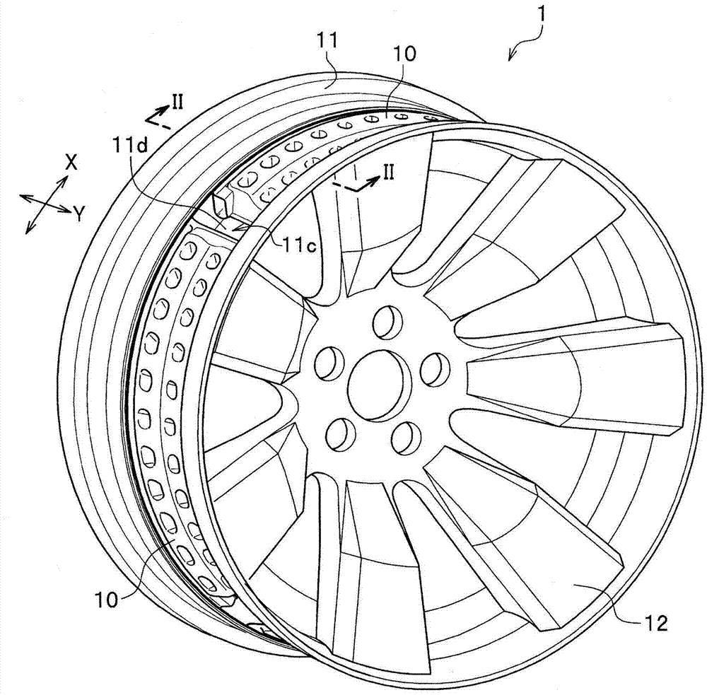
[0064] figure 1 It is a perspective view of a vehicle wheel 1 according to an embodiment of the present invention.

[0065] Such as figure 1 As shown, the vehicle wheel 1 of the present embodiment has a plurality of sub-chamber members 10 as Helmholtz resonators at equal intervals along the wheel circumferential direction X. In addition, in this embodiment, it is assumed that there are four sub-air chamber members 10.

[0066] The vehicle wheel 1 of the present embodiment includes a rim 11 and a wheel 12 for connecting the rim 11 and a hub (not shown). The sub-air chamber member 10 is fitted and mounted on the outer peripheral surface 11d of the concave portion 11c in the rim 11.

[0067] Hereinafter, after describing the rim 11, the sub-air chamber member 10 will be described.

[0068]

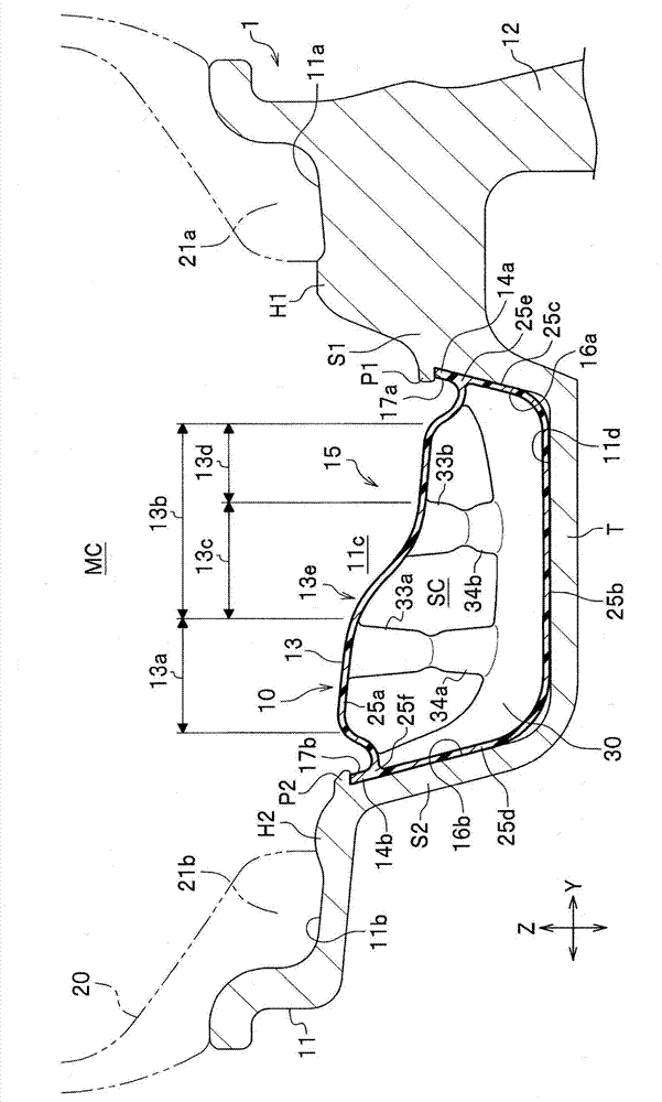
[0069] figure 2 Yes figure 1 Partial enlarged cross-sectional view ...


PUM


Abstract

The present invention provides a vehicle wheel including a sub-air chamber member capable of securing a sufficiently larger volume of the sub-air chamber than conventional ones. The vehicle wheel (1) of the present invention is characterized in that the main body portion (13) of the auxiliary air chamber member (10) is aligned with one end in the wheel width direction (Y) when viewed in cross section along the wheel width direction (Y). side (second region (13b) side), the other end side (first region (13a) side) on the outer peripheral surface (11d) of the concave portion (11c) is formed higher in height, the main body portion (13) Compared with the position (hel) of the edge portion (14a) on the one end side, the position (he2) of the edge portion (14b) on the other end side is toward the wheel radial direction (Z) of the two edge portions (14a, 14) of Lateral offset.

Description

Technical field [0001] The present invention relates to wheels for vehicles. Background technique [0002] Conventionally, as a wheel that muffles air column resonance in a tire air chamber, there is known a structure in which a sub-air chamber member that functions as a Helmholtz resonator in the tire air chamber is provided on the outer peripheral surface of the concave portion (For example, refer to Patent Document 1). [0003] The auxiliary air chamber member of the wheel includes a main body part having an auxiliary air chamber communicating with the tire air chamber on the inner side. And the upper surface of the main body part becomes a flat surface substantially parallel to the outer peripheral surface of the recessed part. [0004] 【Prior Technical Literature】 [0005] 【Patent Literature】 [0006] [Patent Document 1] Japanese Patent No. 4551422 [0007] [Problems to be solved by the invention] [0008] However, in order for the sub-chamber member to fully exhibit its performan...

Claims


Application Information

Patent Timeline
Patent Type & Authority Patents(China)
IPC IPC(8): B60B7/00
Inventor 神山洋一石井克史
Owner HONDA MOTOR CO LTD
Why Eureka
Try Eureka