
Electrically driven two-wheeled vehicle

An electric two-wheel and electric motor technology, which is applied to electric vehicles, electric scooters, motor vehicles, etc., can solve the problems of complicated charging operation, and achieve the effect of improving convenience and easy charging operation.

Active Publication Date: 2012-06-13
HONDA MOTOR CO LTD
View PDF7 Cites 9 Cited by
  • Summary
  • Abstract
  • Description
  • Claims
  • Application Information

AI Technical Summary

Problems solved by technology

[0004] In the technology disclosed in Patent Document 1, the charger connected to the storage battery is arranged under the storage box, and the power receiving side connection terminal connected to the charger is provided at the front of the storage box. When charging from an external power source, it is necessary to open the passenger seat above the storage box, which not only complicates the charging operation, but also requires the passenger seat to be always open in the charging state. , it is hoped that the charging operation can be carried out in the state where the seat for riding is closed

Method used


Image

  • Electrically driven two-wheeled vehicle
  • Electrically driven two-wheeled vehicle
  • Electrically driven two-wheeled vehicle

Examples


Embodiment 1

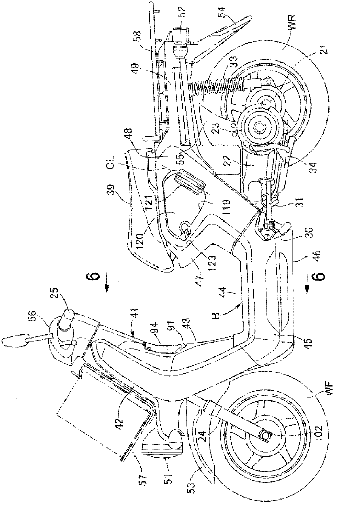
[0098] refer to Figure 1 to Figure 14 Embodiment 1 of the present invention is described, at first, in figure 1 Among them, the electric two-wheeled vehicle is a scooter-type electric two-wheeled vehicle having a low floor 44, and is configured to drive the rear wheel WR to rotate by the output rotational force of the electric motor 23 built in the swing arm 22, The swing arm 22 pivotally supports an axle 21 of a rear wheel WR as a driving wheel at the rear.

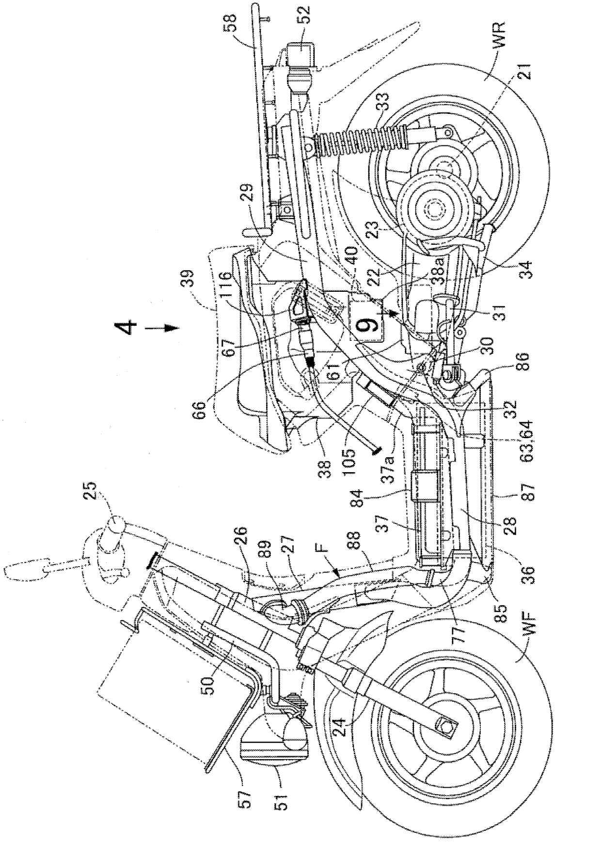
[0099] exist figure 2 Among them, the body frame F of the electric two-wheeled vehicle is provided with: a head pipe 26, which can steerably support a front fork 24 and a steering handle 25, the front fork 24 pivotally supports the front wheel WF, and the steering handle 25 and the front fork 24 The lower frame 27 extending backward and downward from the head pipe 26; a pair of left and right underframes 28 connected to the lower part of the down frame 27 and extending backward; and the above-mentioned underframe 28....

Embodiment 2

[0153] refer to Figure 15 ~ Figure 20 , the second embodiment of the present invention will be described, however, only the parts corresponding to the first embodiment are denoted by the same reference numerals, and the detailed description will be omitted.

[0154] First, in Figure 15 In the rear of the passenger seat 39 and on the upper part of the rear cover 49, a shelf 59 having a flat surface 59a for loading goods is provided, and a shelf 59 that is higher than the flat surface 59a is provided at the front of the shelf 59. The protruding restricting portion 59b forms a space S between the restricting portion 59b and the rear end of the riding seat 39 when the vehicle is viewed from the side. Moreover, the rear stand 58 arrange|positioned above the shelf 59 is detachably attached to the rear frame 29....

[0155] merge reference Figure 16 ~ Figure 19 The storage box 38 is formed in a box shape with an open upper end, and the upper end opening is closed by the vehicle...


PUM


Abstract

An electrically driven two-wheeled vehicle provided with an electric motor which generates power for driving the rear wheel, a battery which supplies electric power to the electric motor, a sitting seat on which the occupants sits, a containing box which is disposed below the sitting seat, and a side cover which covers the containing box at a position below the sitting seat, wherein the battery is rechargeable. An opening (118) which is covered with an openable / closable lid member (120) is provided in the side cover (48), and an electricity receiving-side connector (67) which can be inserted into an electricity supply-side connector which connects to an external electric power source is affixed and disposed between the containing box and the outer surface of the side cover (48) so as to be exposed at the opening (118). The configuration eliminates the need of opening the sitting seat in order to recharge the battery, and as a result, the recharging operation is facilitated.

Description

technical field [0001] The present invention relates to an electric two-wheeled vehicle comprising: a motor that outputs power to drive rear wheels, a battery that supplies power to the motor, a seat for a passenger to sit on, and a vehicle seat disposed under the seat for a vehicle. The storage box and the side cover covering the storage box under the passenger seat can charge the storage battery. Background technique [0002] Patent Document 1 already discloses that, in an electric scooter running by driving a rear wheel with driving force output from an electric motor, a charger can charge a battery that supplies electric power to the electric motor. [0003] Patent Document 1: Japanese Patent No. 3336529 [0004] In the technology disclosed in Patent Document 1, the charger connected to the storage battery is placed under the storage box, and the receiving-side connection terminal connected to the charger is provided at the front of the storage box. When charging from ...

Claims


Application Information

Patent Timeline
Patent Type & Authority Applications(China)
IPC IPC(8): B62J99/00B60K8/00B62H1/02B62J23/00
CPCB60K11/06B62K11/10Y02T90/14Y02T10/7241B60K11/08Y02T90/121B60K2015/053B60K1/04B60Y2200/12Y02T10/7005B60K15/05B60L11/1868B60K7/0007B60Y2200/126B60K2007/0053Y02T10/7216B62K2204/00B60L2210/10B60L2230/12Y02T10/705B62K2202/00Y02T10/7066B60K2015/0553B62J17/00B60K2007/0061Y02T90/127B62K2208/00B60L11/1877B62K19/30B60K2001/005B60L2200/12B60L2210/30Y02T10/7088B60L11/1818B60L2220/46B60L53/16B60L58/20B60L50/66B60L53/18Y02T10/70Y02T10/7072Y02T10/72B62J43/28B62J43/16B62J23/00B62J9/14B62J11/19B62K11/02B62J99/00B60K8/00B62H1/02Y02T90/12
Inventor 中村正典佐藤良山中伯纯中川英亮皆川达也细田哲郎
Owner HONDA MOTOR CO LTD
Learn More