a wind brace

A technology for wind bracing and positioning components, which is used in buildings, building fastening devices, and wing sash fastening devices, etc., which can solve problems such as being hard to be blown by strong winds, reducing the overall strength of window sashes, and positioning the wind bracing thickness and thickness.

Active Publication Date: 2017-03-01
SHENZHEN HOPO WINDOW CONTROL TECH CO LTD
View PDF5 Cites 2 Cited by
  • Summary
  • Abstract
  • Description
  • Claims
  • Application Information

AI Technical Summary

Problems solved by technology

[0002] In the prior art, the positioning of wind braces generally adopts the positioning method of racks meshing with each other, such as Figure 8 As shown, that is, when the transmission plate 121 slides back and forth, the protrusion arranged on the transmission plate 121 interferes with the circular convex point at the bottom of the lower rack 10, so that the lower rack 10 moves upward and connects with the upper rack at one end of the connecting rod 21. 9 are engaged with each other, thereby making the window sash connected with the other end of the connecting rod 21 positioned; as Figure 9 As shown, when the protrusion on the transmission plate 121 is separated from the circular convex point at the bottom of the lower rack 10, the lower rack 10 moves downward and separates from the upper rack 9 at one end of the connecting rod 21, thereby making the connection with the connecting rod 21 The window sash connected at the other end can be adjusted freely. The positioning wind bracing of the above structural design has a relatively thick positioning wind bracing after assembly, such as Figure 10 As shown, when matching with the standard window sash C slot 71, it is necessary to destroy the bottom surface of the C slot before assembling. The positioning wind brace installed in this way greatly reduces the overall strength of the window sash; The positioning method of meshing with each other makes the window sash in a locked state after positioning, that is, when the window sash is blown by strong wind, it is difficult to be automatically closed by strong wind, so it is easy to cause damage to the positioning wind brace

Method used


Image

  • a wind brace
  • a wind brace
  • a wind brace

Examples


Embodiment Construction

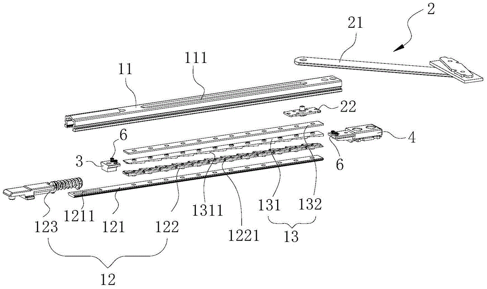
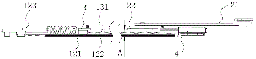
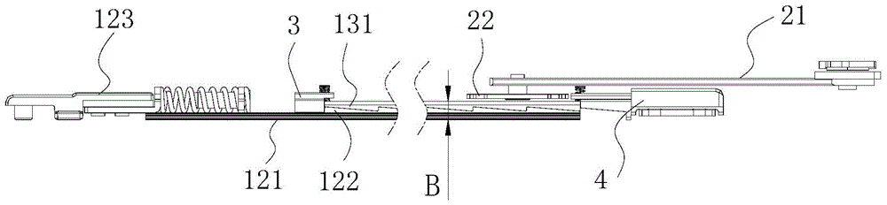
[0033] Attached below Figure 1 to Figure 7 and Figure 11 The technical solutions of the present invention are further described through specific implementation methods.

[0034] Such as figure 1 and Figure 4 As shown, a positioning wind brace includes a wind brace positioning assembly 1, and a connecting rod assembly 2 connected with the wind brace positioning assembly 1, the connecting rod assembly 2 includes a connecting rod 21, and is connected with the connecting rod One end of 21 is pivotally connected to the sliding piece 22; the wind brace positioning assembly 1 includes a slide rail 11 for sliding the slide piece 22, a handle transmission piece 12 slidingly matched with the slide rail 11, and a The handle transmission part 12 cooperates with the extruding part 13 for the sliding part 22 to stop sliding; the setting of the extruding part 13 can form a certain friction force with the sliding part 22, and then play a role in the positioning of the window sash. Eff...


PUM


Abstract

The invention discloses a positioning wind brace which comprises a wind brace positioning assembly and a connection rod assembly, wherein the connection rod assembly comprises a connection rod and a sliding piece; the wind brace positioning assembly comprises a sliding rail on which the sliding piece slides, a handheld transmission piece matched with the sliding rail in a sliding manner and an extrusion piece; when the handheld transmission piece forwards slides along the sliding rail, the extrusion piece upwards moves, so that the sliding piece and the sliding rail are closely extruded; at the moment, the sliding piece stops sliding, and a window sash angle is fixed; when the handheld transmission piece backwards slides along the sliding rail, the extrusion piece downwards moves, and the sliding piece and the sliding rail are separated; at the moment, the sliding piece can continuously slide, and the window sash angle can be adjusted. Due to the structural design, by transmission of the handheld transmission piece, the extrusion piece extrudes the sliding piece tightly; therefore, positioning of a window sash is realized; furthermore, the phenomenon that the positioning wind brace is broken because the window sash is locked after being positioned can be effectively avoided.

Description

technical field [0001] The invention relates to the technical field of wind braces, in particular to a positioning wind brace. Background technique [0002] In the prior art, the positioning of wind braces generally adopts the positioning method of racks meshing with each other, such as Figure 8 As shown, that is, when the transmission plate 121 slides back and forth, the protrusion arranged on the transmission plate 121 interferes with the circular convex point at the bottom of the lower rack 10, so that the lower rack 10 moves upward and connects with the upper rack at one end of the connecting rod 21. 9 are engaged with each other, and then the window sash connected with the other end of the connecting rod 21 is positioned; as Figure 9 As shown, when the protrusion on the transmission plate 121 is separated from the circular convex point at the bottom of the lower rack 10, the lower rack 10 moves downward and separates from the upper rack 9 at one end of the connecting ...

Claims


Application Information

Patent Timeline
Patent Type & Authority Patents(China)
IPC IPC(8): E05C17/20
Inventor 李树鹏林洲
Owner SHENZHEN HOPO WINDOW CONTROL TECH CO LTD
Why Eureka
Try Eureka