
A hydraulic cylinder lateral force loading device for simulating working conditions

A technology of loading device and hydraulic cylinder, which is applied in the direction of fluid pressure actuation device, fluid pressure actuation system test, mechanical equipment, etc. It can solve problems such as not conforming to actual working conditions, achieve perfect detection technology, and facilitate adjustment and disassembly , the effect of compact structure

Active Publication Date: 2017-03-15
NANJING UNIV OF SCI & TECH +1
View PDF8 Cites 0 Cited by
  • Summary
  • Abstract
  • Description
  • Claims
  • Application Information

AI Technical Summary

Problems solved by technology

The loading device of the oil cylinder test device only includes a radial loading device, that is, its test method only includes the situation that the hydraulic cylinder is subjected to lateral load when it is running without load, and it is forbidden to apply lateral force when the hydraulic cylinder is working normally, and in most cases it is Under load, it is affected by lateral force, and the application position of the lateral force device is applied to the extension end of the piston rod from bottom to top. In the actual work of the hydraulic cylinder, the part subjected to lateral force is mostly the earring at the end of the piston rod. Therefore, the test method and test device do not conform to the actual working conditions.

Method used


Image

  • A hydraulic cylinder lateral force loading device for simulating working conditions
  • A hydraulic cylinder lateral force loading device for simulating working conditions
  • A hydraulic cylinder lateral force loading device for simulating working conditions

Examples


Embodiment Construction

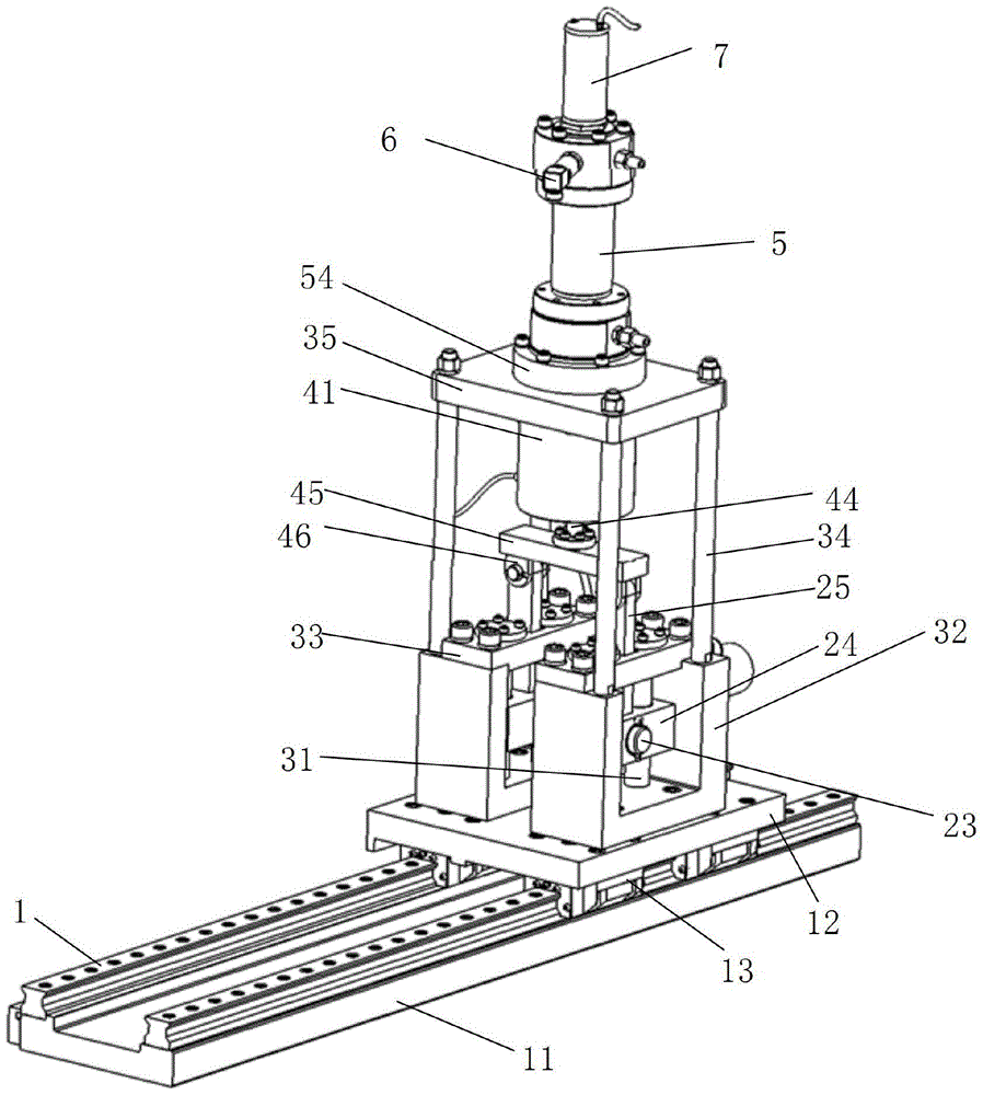
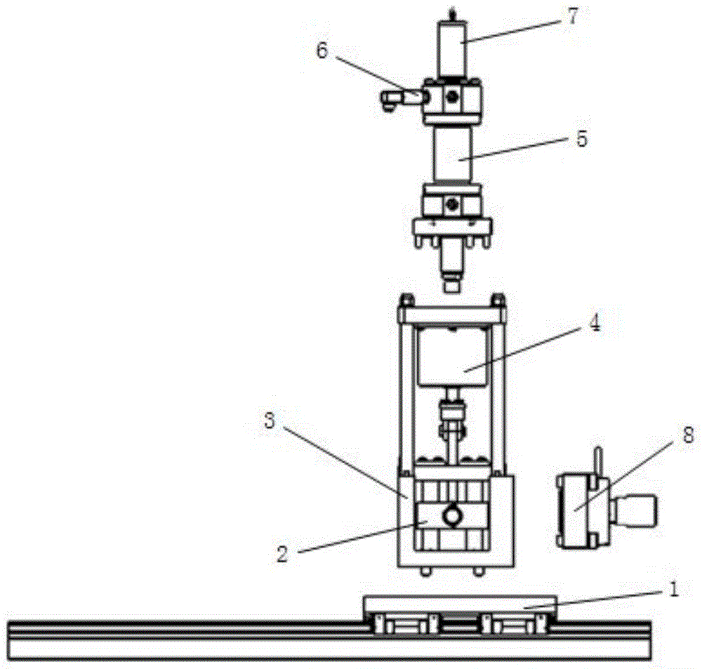
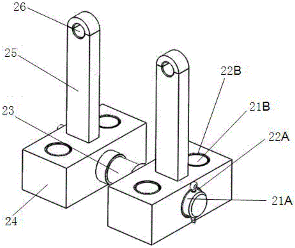
[0027] to combine figure 1 and figure 2 , a hydraulic cylinder lateral force loading device for simulating working conditions, including a linear guide rail 1, a sliding seat 2, and a fixed seat 3, the linear guide rail 1 is welded on the bottom surface 11 of the guide rail installation, and the guide rail base 12 fixes the slider 13 by bolts Under the platform, for linear motion along the linear guide rail 1, the fixed seat 3 is arranged on the guide rail base, the earring of the piston rod extension end of the hydraulic cylinder under test is fixed on the sliding seat 2, and the sliding seat 2 is arranged on the fixed seat 3 and The sliding seat 2 moves in a direction perpendicular to the linear guide rail 1; external forces act on the fixed seat 3 and the sliding seat 2 respectively to apply axial force and lateral force to the piston of the hydraulic cylinder under test.

[0028] to combine image 3 In order to realize that the sliding base 2 moves in a direction perpen...


PUM


Abstract

The invention discloses a working condition simulating hydraulic cylinder lateral force loading device which comprises a straight line guiding track, a sliding base and a fixing base. A guiding track base which moves along a straight line is arranged on the straight line guiding track. The fixing base is arranged on the guiding track base. An earring of an extending end of a piston rod of a tested hydraulic cylinder is fixed on the sliding base. The sliding base is arranged on the fixing base and moves in the direction perpendicular to the straight line guiding track. External force acts on the fixing base and the sliding base respectively, and axial force and lateral force are applied to a piston of the tested hydraulic cylinder respectively. The loading device can specifically simulate bearing situations of different forms under the effect of lateral force of the hydraulic cylinder, the working situation of the hydraulic cylinder under the lateral force load during standing can be simulated, and the working situation of the hydraulic cylinder under the lateral load during moving can be simulated.

Description

technical field [0001] The invention relates to the field of test equipment in hydraulic cylinder technology, in particular to a hydraulic cylinder lateral force loading device for simulating working conditions. Background technique [0002] For hydraulic cylinders, lateral force will be generated in normal use, but for hydraulic cylinders of different types and under different working conditions, the magnitude of the lateral force and its influencing factors are also quite different, and the form of damage caused by it is also different. More numerous. Its common problems, such as abnormal noise, crawling, oil leakage, and even damage to structural parts, may cause the host system to fail to work normally. At present, there are few studies on the lateral force of hydraulic cylinders in the entire industry, and it is difficult to accurately predict the different forms of hydraulic cylinders subjected to lateral forces and the hazards that occur when they are subjected to la...

Claims


Application Information

Patent Timeline
Patent Type & Authority Patents(China)
IPC IPC(8): F15B19/00
CPCF15B19/00
Inventor 张卫王宇恒汪晟杰张鸿鹄郭莲马赛平钟坤马宇辰吉倩陆宝春
Owner NANJING UNIV OF SCI & TECH
Learn More