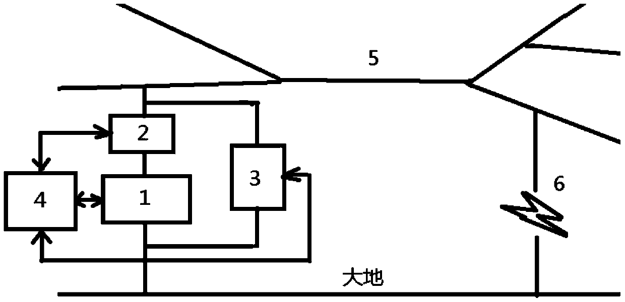
A method for distance measurement of arc-flash ground faults in power supply lines
A technology for power supply lines and ground faults, which is applied in the field of power systems, can solve problems such as measurement process interference, unsatisfactory results, and deviations in ranging results, and achieve the effects of simple calculation procedures, fast measurement speed, and easy realization
- Summary
- Abstract
- Description
- Claims
- Application Information
AI Technical Summary
Problems solved by technology
Method used
Image
Examples
Embodiment 1
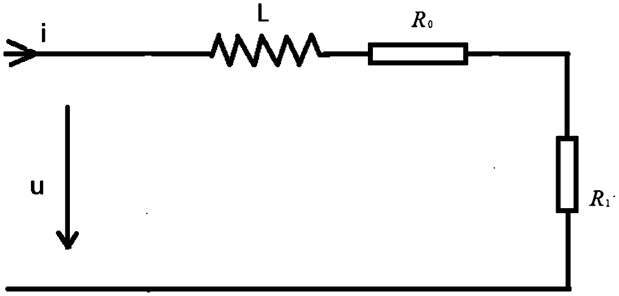
[0041] Such as figure 2 Shown is the first-order fault equivalent circuit diagram of the faulty line. In the figure, L is the equivalent inductance of the line between the current injection point and the fault breakdown point, which is proportional to the fault distance; R 0 is the line equivalent resistance between the current injection point and the fault breakdown point, which is proportional to the fault distance; R 1 is the ground transition resistance after fault breakdown.
[0042] Perform Laplace transform on the first-order fault equivalent circuit to obtain its transfer function, after discretization, obtain a discrete pulse transfer function, use the dynamic system identification method to obtain the parameters of the pulse transfer function, and obtain by solving the equation The transfer function parameters of the continuous system, and then calculate the equivalent inductance L in the equivalent circuit, and divide L by the inductance per unit length of the fa...
Embodiment 2
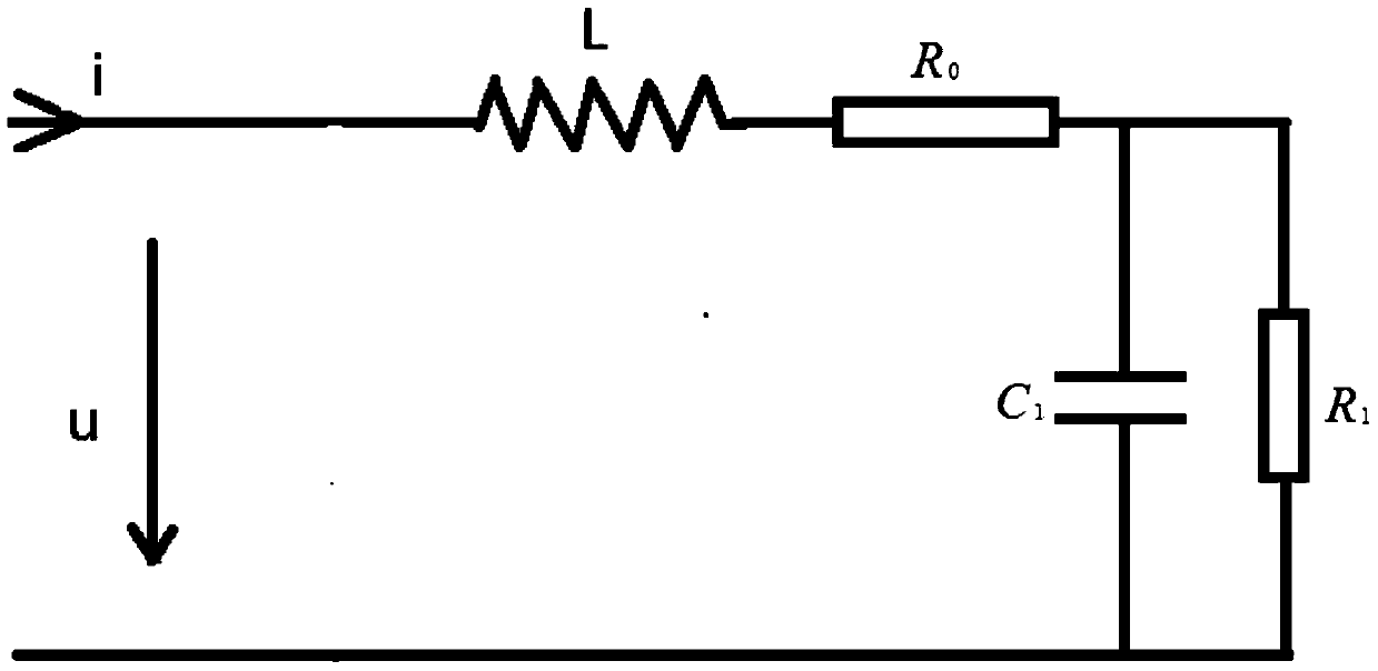
[0044] Such as image 3 Shown is the second-order fault equivalent circuit diagram of the faulty line. In the figure, L is the equivalent inductance of the line between the current injection point and the fault breakdown point, which is proportional to the fault distance; R 0 is the line equivalent resistance between the current injection point and the fault breakdown point, which is proportional to the fault distance; R 1 is the ground transition resistance after fault breakdown, C 1 It is the equivalent capacitance converted from the fault line to the fault point.
[0045] Perform Laplace transform on the second-order fault equivalent circuit to obtain its transfer function, after discretization, obtain a discrete pulse transfer function, use the dynamic system identification method to obtain the parameters of the pulse transfer function, and obtain by solving the equation The transfer function parameters of the continuous system, and then calculate the equivalent inducta...
Embodiment 3
[0047] Such as Figure 4 Shown is the third-order fault equivalent circuit diagram of the faulty line. In the figure, L is the equivalent inductance of the line between the current injection point and the fault breakdown point, which is proportional to the fault distance; R 0 is the line equivalent resistance between the current injection point and the fault breakdown point, which is proportional to the fault distance; R 1 is the ground transition resistance after fault breakdown, C 0 is the equivalent capacitance converted from the line capacitance to the current injection point, C 1 It is the equivalent capacitance converted from the line capacitance to the fault point. The line capacitance includes each branch line, the line between the fault point and the current injection point, and the line capacitance between the fault point and the end of the line.
[0048] Perform Laplace transform on the third-order fault equivalent circuit to obtain its transfer function, after ...
PUM
 Abstract
Description
Claims
Application Information
 - R&D
- Intellectual Property
- Life Sciences
- Materials
- Tech Scout
- Unparalleled Data Quality
- Higher Quality Content
- 60% Fewer Hallucinations
Browse by: Latest US Patents, China's latest patents, Technical Efficacy Thesaurus, Application Domain, Technology Topic, Popular Technical Reports.
© 2025 PatSnap. All rights reserved.Legal|Privacy policy|Modern Slavery Act Transparency Statement|Sitemap|About US| Contact US: help@patsnap.com


