Asymmetric Phase Encoding Ranging Method for LiDAR System

A laser radar and phase encoding technology, applied in radio wave measurement systems, measurement devices, and use of re-radiation, etc., can solve the problem that the total signal bandwidth of the array detector and the signal processor is difficult to meet the real-time detection of the system, and the number of detector pixels is large. and other problems, to avoid high-speed acquisition, reduce computing resources, and minimize mutual interference.

CN104931973BActive Publication Date: 2017-05-10ZHEJIANG SCI-TECH UNIV
4 Cites 0 Cited by

Patent Information

Authority / Receiving Office
CN · China
Patent Type
Patents(China)
Current Assignee / Owner
Publication Date
2017-05-10

Smart Images

  • Figure 1
    Figure 1
  • Figure 2
    Figure 2
  • Figure 3
    Figure 3
Patent Text Reader

Abstract

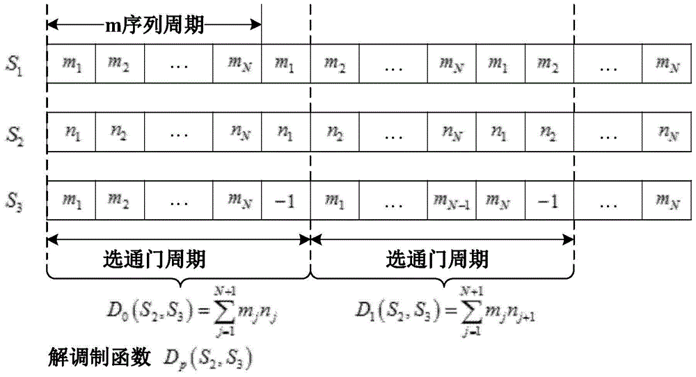
The invention discloses an asymmetrical phase encoding ranging method for a laser radar system. Typical phase encoding methods used in lidar systems place high demands on the system hardware. The steps of the present invention are as follows: the laser in the laser radar system emits a laser signal with constant intensity, and the modulator performs intensity modulation according to the modulation signal sequence; the modulation signal sequence adopts m sequence; the demodulator performs intensity modulation on the echo signal according to the demodulation signal sequence Demodulation; use gating mode to control the cumulative detection time and output of the detector; the detector outputs the accumulated signal to the signal processor; the order of the detector output signal shows the position of the correlation peak, so that the signal processor directly judges the demodulation The phase difference between the signal and the echo signal; according to the phase difference, the target distance is calculated. The invention adopts the asymmetrical phase coding method to measure the target distance, reduces the requirement of the system on the sampling rate of the detector, and reduces the calculation amount of signal processing.
Need to check novelty before this filing date? Find Prior Art

Description

technical field

[0001] The invention belongs to the field of laser radar, and in particular relates to an asymmetric phase encoding ranging method used in a laser radar system. Background technique

[0002] The typical phase encoding method used in the laser radar system modulates the phase of the light wave carrier frequency signal according to the code source, and then transmits the phase encoded laser pulse signal. The laser signal reflected by the target is converged on the detector through the optical system, and the detector is converted into an echo The coded electrical pulse signal is sent to the signal processor together with the demodulation signal, and the correlation calculation is completed in the signal processor, and finally the distance parameter of the target is given. However, the detection of phase-encoded signals requires a high-speed detector to sample the signal quickly and the signal processor to process it quickly, which puts high demands on the syste...

Examples

Embodiment Construction

[0042] The present invention will be further described below in conjunction with the accompanying drawings and embodiments.

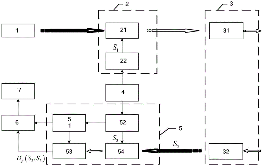
[0043] Such as figure 1 with 2 As shown, the asymmetric phase encoding ranging method used in the laser radar system adopts the asymmetric phase encoding laser radar system, including a laser 1, a laser modulation unit 2, an optical antenna 3, a pulse signal generator 4, a laser detection unit 5, Signal processor 6 and computer 7; Laser modulation unit 2 comprises modulator 21 and first signal source 22, optical antenna 3 comprises optical transmitting antenna 31 and optical receiving antenna 32, and laser detection unit 5 comprises gate controller 51, the first Two signal sources 52 , detectors 53 and demodulators 54 .

[0044]Optical path: the laser 1 is used to emit a laser signal of constant intensity. The laser emitting end of the laser 1 is connected to the optical input end of the modulator 21 , and the optical output end of the modulator 21 is...