Gas turbine engine with multiple component exhaust diffuser operating in conjunction with an outer case ambient external cooling system

An exhaust diffuser, gas turbine technology, applied in the direction of machines/engines, engine components, engine manufacturing, etc., can solve problems such as cracks, failures, bearing support column cracks, etc.

Inactive Publication Date: 2015-09-23
SIEMENS ENERGY INC
View PDF7 Cites 6 Cited by
  • Summary
  • Abstract
  • Description
  • Claims
  • Application Information

AI Technical Summary

Problems solved by technology

Extra stress (operating in combination with low cycle fatigue) can lead to cracking, rupture or failure of the bearing support struts (mounted to the housing to support the exhaust end bearing cage)

Method used


Image

  • Gas turbine engine with multiple component exhaust diffuser operating in conjunction with an outer case ambient external cooling system
  • Gas turbine engine with multiple component exhaust diffuser operating in conjunction with an outer case ambient external cooling system
  • Gas turbine engine with multiple component exhaust diffuser operating in conjunction with an outer case ambient external cooling system

Examples


Embodiment Construction

[0029] In the following detailed description of the preferred embodiments, reference is made to the accompanying drawings which form a part hereof, and in which are shown by way of illustration only and not by way of limitation certain preferred embodiments in which the invention may be practiced. It is to be understood that other embodiments may be utilized and changes may be made without departing from the spirit and scope of the invention.

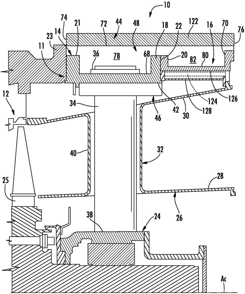
[0030] see figure 1 , shows a portion of the exhaust section 10 of the gas turbine engine axially downstream of the turbine section 12 to illustrate aspects of the invention. Exhaust section 10 generally includes a cylindrical structure comprising C The circumferentially extending casing 11, the exhaust portion forms the downstream extension of the casing of the gas turbine engine. The housing 11 of the exhaust section 10 includes an exhaust stack or turbine exhaust casing 14 and an exhaust spool structure 16 downstream of the exhaust...


PUM


Abstract

An attachment system for attaching at least one exhaust diffuser (26) downstream from a turbine assembly (12) in a gas turbine engine is disclosed. The attachment system may include at least one attachment flange (134) extending from a downstream edge (132) and attached to a spring plate diffuser support structure (202) and at least one attachment flange (134) extending from side edges of the exhaust diffuser (26) to couple sections of the exhaust diffuser (26) together. The diffuser (26) may also include a thermal barrier/cooling system (44) for controlling a temperature of an outer case (11) of the gas turbine engine. The thermal barrier/cooling system (44) may form a flow path for an ambient air flow cooling.

Description

[0001] Cross References to Related Applications [0002] This application is a continuation-in-part of US Patent Application 13 / 314311 filed on November 8, 2011. technical field [0003] The present invention relates to gas turbine engines, and more particularly, to structures that provide thermal security to limit heating of the casing of the gas turbine engine. Background technique [0004] A gas turbine engine typically includes a compressor section, a combustor section, a turbine section and an exhaust section. In operation, the compressor section can receive ambient air and compress the ambient air. Compressed air from the compressor section enters one or more combustors in the combustor section. The compressed air is mixed with fuel in a combustor where the air-fuel mixture is burned to form hot working gases. The hot working gas is passed to the turbine section where it is expanded through alternating rows of stationary and rotating airfoils and used to generate po...

Claims


Application Information

Patent Timeline
Patent Type & Authority Applications(China)
IPC IPC(8): F01D25/30F01D25/24F01D25/12F01D9/06
CPCF01D25/12F05D2260/30F01D9/065F05D2250/182F01D25/30F01D25/243
Inventor M.芒希J.W.芬纳兰Y.施特曼D.J.格雷伯M.R.波特J.M.利冈
Owner SIEMENS ENERGY INC
Why Eureka
Try Eureka