Drill bit

A technology of drill bit and drill arm, which is applied in the field of drill bits of pile sinking and reaming machines, can solve the problems of insufficient strength and hardness of spiral pouring piles, long formation period of spiral pouring piles, and inability to carry out pile pressing work, etc., and achieves simple structure, The effect of uniform force and large mediation range

Inactive Publication Date: 2015-09-30
JIANGSU GOODENG ENG MACHINERY ASSEMBLING
View PDF0 Cites 3 Cited by
  • Summary
  • Abstract
  • Description
  • Claims
  • Application Information

AI Technical Summary

Problems solved by technology

[0002] Existing pile drivers include static pile drivers, pneumatic hammer pile drivers, and spiral pouring pile drivers. Traditional static pile drivers are difficult to press piles in geological layers such as sand layers, hard soil layers, and differentiated layers, and even Under some geological conditions, the traditional static pile driver cannot carry out the pile pressing work, and the static pile driver has a high degree of damage to geological layered piles such as sand layers, hard soil layers, and differentiated layers.
The piles formed by spiral irrigation also have many shortcomings, such as: the strength and hardness of the spiral irrigation piles are not good enough, and the formation period of the spiral irrigation piles is long
[0003] During the construction of the traditional static pile driver, the pile is directly held and the pile is statically pressed downward without drilling or reaming. Pile is difficult, even under some geological conditions, the traditional static pile driver cannot carry out the pile pressing work

Method used


Image

  • Drill bit
  • Drill bit
  • Drill bit

Examples


Embodiment Construction

[0017] In order to make the above objects, features and advantages of the present invention more comprehensible, the present invention will be further described in detail below in conjunction with specific embodiments.

[0018] First of all, "one embodiment" or "embodiment" referred to herein refers to a specific feature, structure or characteristic that may be included in at least one implementation of the present invention. "In one embodiment" appearing in different places in this specification does not all refer to the same embodiment, nor is it a separate or selective embodiment that is mutually exclusive with other embodiments.

[0019] Secondly, the present invention is described in detail using structural schematic diagrams, etc. When describing the embodiments of the present invention in detail, for the convenience of explanation, the schematic diagrams representing the drill bit structure will not be partially enlarged according to the general scale, and the schematic ...


PUM


Abstract

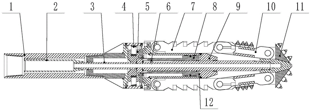
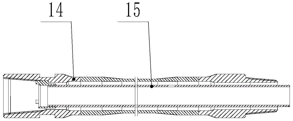
The invention provides a drill bit which comprises a cylinder, a core shaft, a drill arm, a connecting rod drill arm and a precursor drill bit body. The core shaft penetrates through the cylinder, one end of the core shaft is fixed with the precursor drill bit body, the precursor drill bit body is connected with the cylinder through the connecting rod drill arm and the drill arm, the core shaft is connected with a core shaft moving mechanism, the core shaft moving mechanism pushes the core shaft to move, and then the drill arm is made to be opened and closed. The drill bit has the advantages of being in large in contraction angle adjusting range, even in stress, large in structural strength and simple in structure, various drilling and bearizing requirements can be met, and the requirement that a small hole is firstly drilled, and after the required depth is achieved, a large hole is drilled can be met. A static pile driver with the drill bit can enter a pile inner hole to carry out drilling and bearizing work when pile pressing is difficult, the traditional static pile driver can be applied to the occasions where pile pressing is hard, and the use range of the static pile driver is widened.

Description

technical field [0001] The invention relates to the technical field of static pile driving machine hole reaming pile sinking, in particular to a drill bit of a pile driving machine hole reaming machine. Background technique [0002] Existing pile drivers include static pile drivers, pneumatic hammer pile drivers, and spiral pouring pile drivers. Traditional static pile drivers are difficult to press piles in geological layers such as sand layers, hard soil layers, and differentiated layers, and even Under some geological conditions, the traditional static pile driver cannot perform pile pressing work, and the static pile driver has a high degree of damage to geological layered piles such as sand layers, hard soil layers, and differentiated layers. The piles formed by spiral irrigation also have many disadvantages, such as: the strength and hardness of the spiral irrigation piles are not good enough, and the formation period of the spiral irrigation piles is long. [0003] D...

Claims


Application Information

Patent Timeline
IPC IPC(8): E21B10/00E21B10/26
Inventor 陈凤钢戴斌安倪万兵程熙石姚姚
Owner JIANGSU GOODENG ENG MACHINERY ASSEMBLING
Why Eureka
Try Eureka