Low-noise water inlet valve body and method for realizing mute when anti-siphon water inlet valve enters water

A water inlet valve, low-noise technology, applied in the valve's device for absorbing fluid energy, valve details, valve device, etc., can solve the problems that the water inlet valve is difficult to meet the requirements of ENISO3822, it is difficult to find the water inlet valve, and the water is urgent, etc. Achieve the effects of simple structure, low cost and slow water flow of the water inlet valve body

Active Publication Date: 2017-10-31
ECO XIAMEN TECH INC
View PDF5 Cites 0 Cited by
  • Summary
  • Abstract
  • Description
  • Claims
  • Application Information

AI Technical Summary

Problems solved by technology

However, in practice, the outlet water of this structure spirals down along the pipe wall. When the pressure of the water inlet pipe is high, the water outlet is relatively rapid, and it is easy to suck air from the air inlet to generate noise.
[0006] The European water inlet valve standard EN ISO3822 requires that the noise of the water inlet valve should be lower than 20 decibels when the water enters, while Figure C Inlet valve shown is difficult to meet EN ISO3822 requirements
[0007] Therefore, it is difficult to find water inlet valves that meet European standards in the market, especially bottom-entry water inlet valves.

Method used


Image

  • Low-noise water inlet valve body and method for realizing mute when anti-siphon water inlet valve enters water
  • Low-noise water inlet valve body and method for realizing mute when anti-siphon water inlet valve enters water
  • Low-noise water inlet valve body and method for realizing mute when anti-siphon water inlet valve enters water

Examples


Embodiment 1

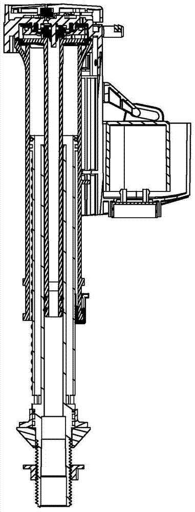
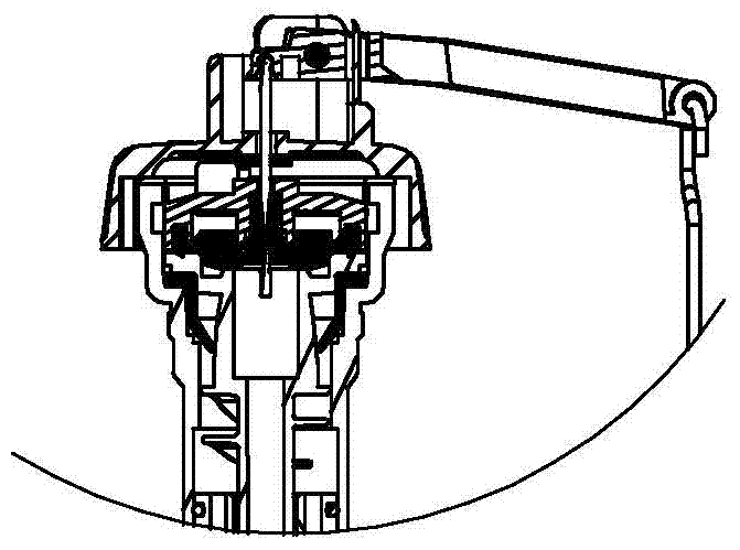
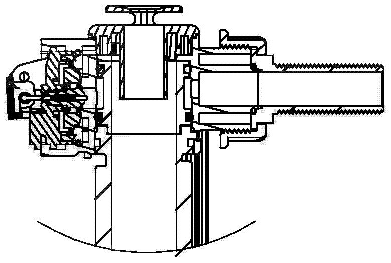
[0077] Such as Figure 1 to Figure 8 The shown low-noise water inlet valve body includes a water inlet valve body 100, a lower casing 200, and an upper casing 300. The lower casing 200 is connected to the water inlet valve body 100 to supply water to the water inlet valve body 100. The upper casing 300 is set between the main body 100 of the water inlet valve and the lower casing 200. The main body of the water inlet valve 100, the lower casing 200 and the upper casing 300 together form a water outlet pipe; the main body of the water inlet valve 100 is higher than the water inlet valve. The position of the highest water level is provided with an air vent 400, and the liquid level in the water inlet valve is directly connected to the atmosphere through the air vent 400 to realize anti-siphon; the water outlet channel 105 of the water inlet valve includes a main waterway 101, several auxiliary waterways 102, the main waterway 101 is directly connected with the water inlet channe...

Embodiment 2

[0085] Such as Figures 16 to 21 The shown low-noise water inlet valve body includes a water inlet valve body 100, a lower casing 200, and an upper casing 300. The lower casing 200 is connected to the water inlet valve body 100 to supply water to the water inlet valve body 100. The upper casing 300 is set between the main body 100 of the water inlet valve and the lower casing 200. The main body of the water inlet valve 100, the lower casing 200 and the upper casing 300 together form a water outlet pipe; the main body of the water inlet valve 100 is higher than the water inlet valve. The position of the highest water level is provided with an air vent 400, and the liquid level in the water inlet valve is directly connected to the atmosphere through the air vent 400 to realize anti-siphon; the water outlet channel 105 of the water inlet valve includes a main waterway 101, several auxiliary waterways 102, the main waterway 101 is directly connected with the water inlet channel 10...

Embodiment 3

[0093] Such as Figures 27 to 33 The shown low-noise water inlet valve body includes a water inlet valve body 100, a lower casing 200, and an upper casing 300. The lower casing 200 is connected to the water inlet valve body 100 to supply water to the water inlet valve body 100. The upper casing 300 is set between the main body 100 of the water inlet valve and the lower casing 200. The main body of the water inlet valve 100, the lower casing 200 and the upper casing 300 together form a water outlet pipe; the main body of the water inlet valve 100 is higher than the water inlet valve. The position of the highest water level is provided with an air vent 400, and the liquid level in the water inlet valve is directly connected to the atmosphere through the air vent 400 to realize anti-siphon; the water outlet channel 105 of the water inlet valve includes a main waterway 101, several auxiliary waterways 102, the main waterway 101 is directly connected with the water inlet channel 103,...


PUM


Abstract

The invention relates to a low-noise water inlet valve. The low-noise water inlet valve comprises a water inlet valve body, a lower sleeve and an upper sleeve. The lower sleeve is connected with a water inlet valve body and supplies water to the water inlet valve body. The upper sleeve is arranged between the water inlet valve body and the lower sleeve in a sleeved mode. The water inlet valve body, the lower sleeve and the upper sleeve jointly form a water outlet pipe. The water inlet valve body is provided with an atmosphere port which is located at the position higher than the highest water level. The liquid surface in the water inlet valve is directly communicated with the atmosphere through the atmosphere port, so that siphon is prevented. A water outlet channel of the water inlet valve comprises a main water way and multiple auxiliary water ways, the main water way is directly communicated with the water inlet channel, the auxiliary water ways are communicated with the main water way, the water outlet speed of the main water way is smaller than the water inlet speed of the water inlet channel, and water overflows to the auxiliary water ways from the main water way, so that water discharge is assisted. By the adoption of the low-noise water inlet valve, in the water inlet process of the water inlet valve, the suction sound is lower, water feeding of the water inlet valve is free of noise, the EN ISO3822 requirement that the noise is lower than 20 db when the water inlet valve feeds water can be met, and the anti-siphon requirement of EN1717 for the water inlet valve can also be met.

Description

technical field [0001] The invention relates to the field of water inlet valves, in particular to a low-noise water inlet valve body and a method for realizing the silence of an anti-siphon water inlet valve when water is ingested. Background technique [0002] The anti-siphon structure of the common water inlet valve on the market is as follows: Figure A , Figure B , Figure C shown. [0003] Figure A , Figure B The shown anti-siphon structure of the water inlet valve is provided with an anti-siphon rubber pad on the water outlet channel. When the water inlet valve fills the water tank, the water pushes the anti-siphon rubber pad to block the air inlet of the water inlet valve to prevent pressure water from leaking. After spraying out, after the water inlet valve stops water injection, the anti-siphon rubber pad resets under the action of gravity or its own elasticity. Keep unimpeded from the air inlet to the water level of the water tank to prevent the water from t...

Claims


Application Information

Patent Timeline
Patent Type & Authority Patents(China)
IPC IPC(8): F16K27/00F16K47/02E03D1/30
CPCE03D1/30F16K27/00F16K47/02
Inventor 杨明昌谢文清吴爱民
Owner ECO XIAMEN TECH INC
Why Eureka
Try Eureka