Dual-butterfly-shaped silver nano optical antenna

An optical antenna, silver nanotechnology, applied in the direction of the radiating element structure and other directions, can solve the problems of insufficient field strength and insufficient stability of the optical antenna, and achieve the effect of strong electric field enhancement effect.

Inactive Publication Date: 2015-09-30
TIANJIN UNIV
View PDF1 Cites 6 Cited by
  • Summary
  • Abstract
  • Description
  • Claims
  • Application Information

AI Technical Summary

Problems solved by technology

However, most of the existing optical antennas are not stable enough, and the generated field strength is insufficient, which causes a lot of inconvenience in actual use

Method used


Image

  • Dual-butterfly-shaped silver nano optical antenna
  • Dual-butterfly-shaped silver nano optical antenna
  • Dual-butterfly-shaped silver nano optical antenna

Examples


Embodiment Construction

[0023] Below in conjunction with accompanying drawing, the present invention will be further described:

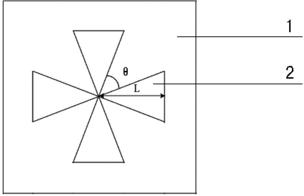
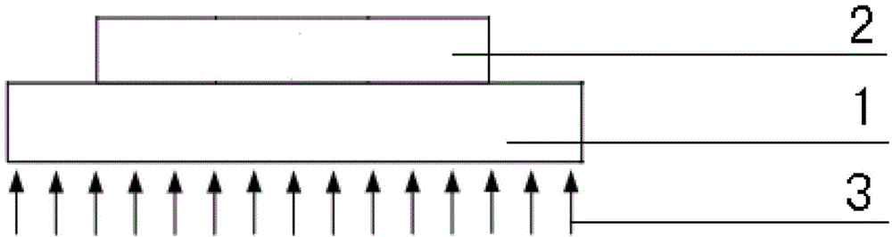
[0024] Such as figure 1 As shown, a double-butterfly silver nano-optical antenna includes a substrate 1 and an antenna arm 2. The antenna arm 2 is arranged on the upper surface of the substrate 1. The size of the substrate 1 is 500nm×500nm×50nm. The substrate 1 The material is a glass medium with a dielectric constant of 1.5. There are four antenna arms 2, all of which are made of silver nanomaterials. The four antenna arms 2 are all of the same triangular structure, and the antenna arms 2 are arranged symmetrically in pairs. The length range L of the antenna arms is 50-100 nm, the angle range θ between adjacent antenna arms is 15°-85°, and the thickness of the antenna arms 2 is 40 nm.

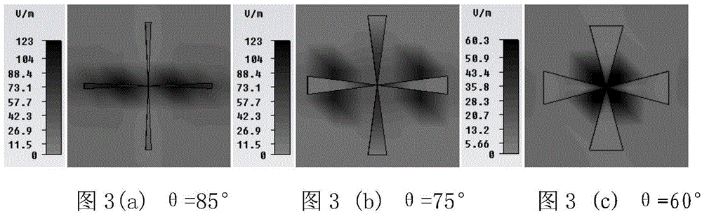
[0025] The characteristics of the optical antenna of the present invention are analyzed through the finite difference time domain algorithm and the local surface plasmon theory simulation...


PUM


Abstract

The invention discloses a dual-butterfly-shaped silver nano optical antenna. The antenna comprises four antenna arms arranged on the upper surface of a substrate, wherein the substrate comprises a glass medium, the antenna arms adopt identical triangular structures respectively and are pairwise symmetrically arranged into dual butterfly shapes, the length of each antenna arm ranges from 50 nm to 100 nm, and the angle formed by every two adjacent antenna arms ranges from 15 degrees to 85 degrees. Effects caused by different parameters, such as the included angles formed by the antenna arms, the length of the antenna arms and different incident light polarization directions, of the dual-butterfly-shaped silver nano optical antenna on near-field electric field distribution and near-field enhancement characteristics are analyzed on the basis of an FDTD (finite difference time domain) algorithm and a localized surface plasmon theory, so that the metal nano optical antenna which works at the optical frequency band, has the higher local field enhancement and has certain stability to the incident light polarization directions is designed.

Description

technical field [0001] The invention relates to the field of nanometer optical antennas, in particular to a double-butterfly silver nanometer optical antenna. Background technique [0002] Metal nano-optical antenna is a metal nano-photonic device that can efficiently couple light waves to sub-wavelength scales. It utilizes the unique optical property of localized surface plasmon (LSPs) resonance of metal nanoparticles. The mutual conversion between the propagation field and the local field is realized. When a light wave is coupled with a metal nanoparticle, the free electrons in the particle will oscillate collectively. When the oscillation frequency of the electron is consistent with the frequency of the incident light wave, LSPs will resonate. During the resonance, the energy is bound near the metal surface, which not only realizes The mutual conversion between the propagating field and the local field is achieved, and a stronger local electric field is also excited. Me...

Claims


Application Information

Patent Timeline
Patent Type & Authority Applications(China)
IPC IPC(8): H01Q1/38
Inventor 金杰王冰张强
Owner TIANJIN UNIV
Why Eureka
Try Eureka