Rotatable orifice plate for direct flow measurement

A flow measurement, orifice plate technology, applied in the detection of fluid flow by measuring differential pressure, volume/mass flow generated by mechanical effects, valve devices, etc., can solve problems such as increasing head loss and occupying space in pressure-related systems

Active Publication Date: 2015-09-30
FLUID HANDLING
View PDF6 Cites 6 Cited by
  • Summary
  • Abstract
  • Description
  • Claims
  • Application Information

AI Technical Summary

Problems solved by technology

These additional components in the system take up additional space and increase the head loss of the pressure dependent sys

Method used


Image

  • Rotatable orifice plate for direct flow measurement
  • Rotatable orifice plate for direct flow measurement
  • Rotatable orifice plate for direct flow measurement

Examples


Embodiment Construction

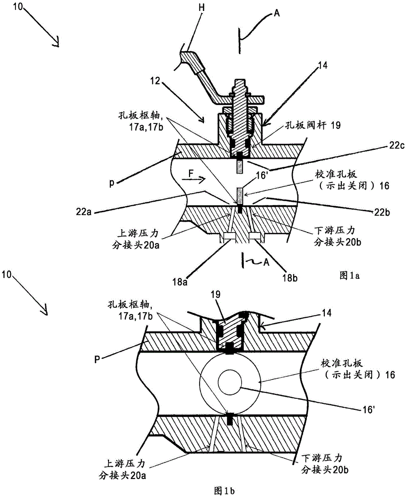
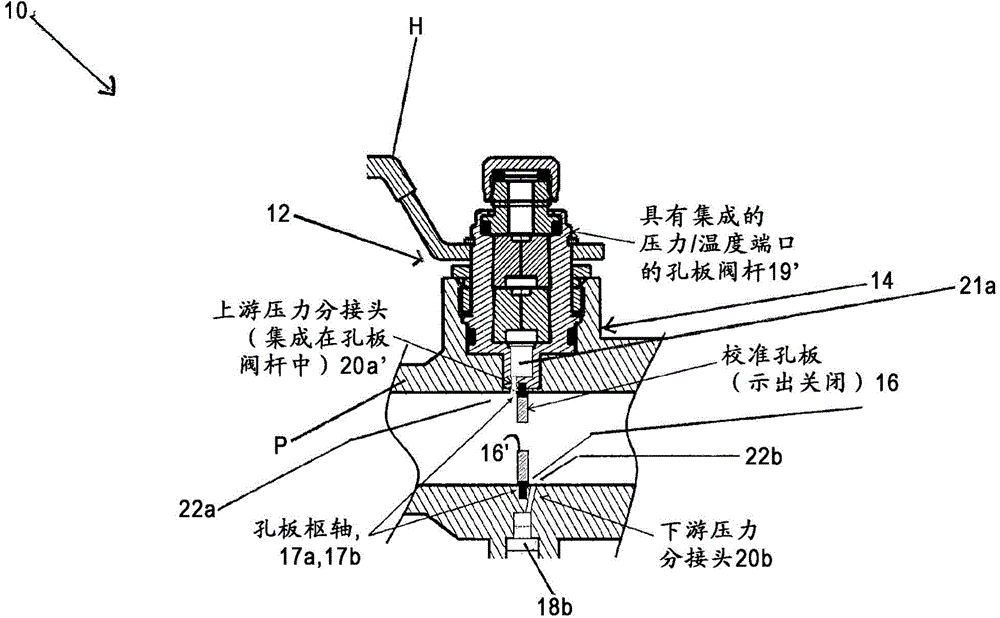
[0014] According to some embodiments, the invention may take the form of an upper device, such as a valve comprising a valve housing or body combined with a rotatable orifice.

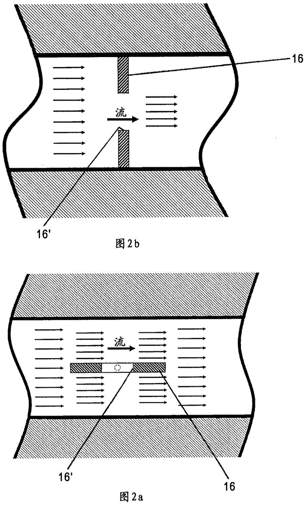
[0015] The valve body or housing may be configured to be disposed within, or form part of, a conduit having a fluid flow, and further configured to have at least one pressure tap disposed at at least one location along said conduit to allow for the flow of the conduit The pressure of the fluid flow is measured. A rotatable orifice having an aperture configured or formed therein and configured to rotate within the valve body or housing about an axis of rotation, the rotatable orifice being positioned along the pipeline at a different location from the at least one pressure tap position for rotation between a first rotatable position providing normal fluid flow operation and a second rotatable position substantially perpendicular to fluid flow providing direct flow measurement of fluid flow such that whe...


PUM


Abstract

A valve is provided having a valve housing/body configured to be arranged in, or form part of, a piping having a fluid flow, and configured with a pressure tap arranged at a location along the piping to allow pressure of the fluid flow of the piping to be measured, and also having a rotatable orifice plate configured to rotate in the valve body/housing on an axis of rotation positioned at a different location along the piping than the pressure tap for rotating between a first rotatable position for providing a normal fluid flow operation and a second rotatable position substantially perpendicular to the fluid flow for providing a direct flow measurement of the fluid flow determined based on signalling sensed by the pressure tap sensor containing information about a measured pressure at the pressure tap when the orifice plate is in the second rotatable position.

Description

[0001] Cross References to Related Applications [0002] This application claims the benefit of Provisional Application Serial No. 61 / 756814 (Attorney Docket No. F-B&G-X0006 / / 911-19.8-1) filed January 25, 2013, which is hereby incorporated by reference in its entirety. [0003] This application is also a continuation-in-part of, and claims the benefit of, Application Serial No. 13 / 681628 (Attorney Docket No. F-B&G-X0003 / / 911-19.6-1) filed November 20, 2012, which is incorporated by reference in its entirety Incorporated into this article. technical field [0004] The present invention relates to techniques for providing direct flow measurement; and more particularly, the present invention relates to a valve configured to provide direct flow measurement. Background technique [0005] Currently, most known systems where fluid flows at a constant rate require a separate permanent flow measurement device to verify the flow rate of the system. These additional components in th...

Claims


Application Information

Patent Timeline
IPC IPC(8): G01F1/36
CPCG01F1/42F16K1/222
Inventor S·P·小埃文斯F·罗斯卡M·奈尔G·维勒卡
Owner FLUID HANDLING
Why Eureka
Try Eureka