Medical equipment belt connecting structure

A connection structure, medical equipment technology, applied in the direction of hospital equipment, medical science, nursing facilities, etc., can solve the problems of safety accidents, no separation of circuit and gas circuit, etc., so as to prevent safety accidents, improve safety level, and facilitate separate maintenance Effect

Inactive Publication Date: 2015-10-07
朱卫
View PDF5 Cites 3 Cited by
  • Summary
  • Abstract
  • Description
  • Claims
  • Application Information

AI Technical Summary

Problems solved by technology

In the usual connection structure of medical equipment, the high and low voltage electrical lines and power supply lines are mixed and laid in one cavity, the circuit and the gas circuit are not separated, and the high and low voltage circuits are not separated, which is prone to safety accidents

Method used


Image

  • Medical equipment belt connecting structure
  • Medical equipment belt connecting structure
  • Medical equipment belt connecting structure

Examples


Embodiment Construction

[0018] The present invention will be described in further detail below in conjunction with the accompanying drawings.

[0019] Figure 1 to Figure 6 Schematically shows a medical device strap connection structure according to an embodiment of the present invention.

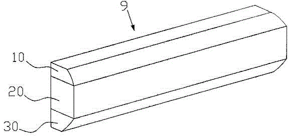
[0020] Such as figure 1 As shown, the medical equipment belt connection structure of the present invention includes a equipment belt body 9, the equipment belt body includes a housing and a channel cavity located inside the housing, the equipment belt body forms a channel cavity by interlocking the housings, and the channel cavity It includes three channels, which are weak current channel cavity 10, gas channel cavity 20 and strong current channel cavity 30. The weak current channel cavity 10 and the strong current channel cavity 30 are located on both sides of the gas channel cavity 20 .

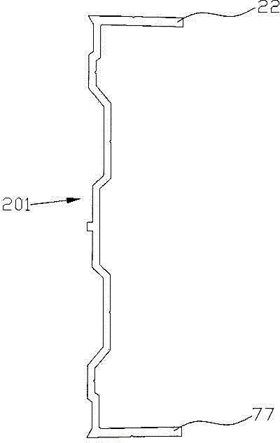
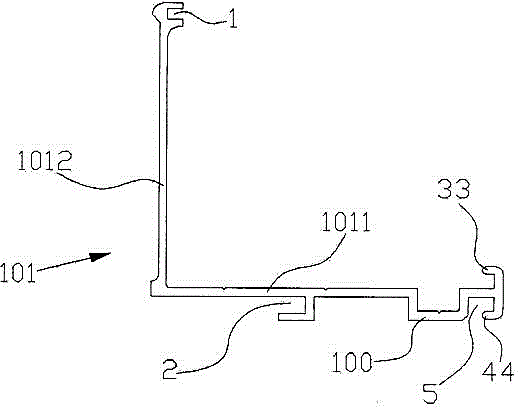
[0021] Such as figure 2 As shown, the connecting structure of medical equipment of the present invention is composed of ...


PUM


Abstract

Invention discloses a medical equipment belt connecting structure. The medical equipment belt connecting structure comprises an equipment belt body. The equipment belt body comprises shells and channel cavities located in the shells. Channel cavities are formed in the equipment belt body in the mode of mutual buckling of the shells. The channel cavities include the weak-current channel cavity, the gas channel cavity and the strong-current channel cavity. A first partition plate is arranged between the weak-current channel cavity and the gas channel cavity. A third partition plate is arranged between the gas channel cavity and the strong-current channel cavity, and the weak-current channel cavity, the gas channel cavity and the strong-current channel cavity are separated through the first partition plate and the third partition plate. According to the medical equipment belt connecting structure, the weak-current channel cavity, the gas channel cavity and the strong-current channel cavity are separated and independent from one another through the partition plates, the structure is reasonable, safety accidents are not likely to happen, the safety grade of an equipment belt is improved, and meanwhile due to the fact that the three cavities are connected in a buckling mode, mounting and dismounting during maintenance are facilitated.

Description

technical field [0001] The invention relates to the field of medical equipment, in particular to a three-chamber separated medical equipment belt connection structure. Background technique [0002] The connecting structure of medical equipment is a commonly used medical device in the ward. It is used to integrate the oxygen source, compressed air source, vacuum source, lamp lighting and communication facilities required by the hospital bed. It is generally installed on the bedside wall of the hospital to provide patients with Various gas connectors, intercom calling system, power socket, lighting and other functions. In the usual connection structure of medical equipment, the high and low voltage electrical lines and power supply lines are mixed and laid in one cavity, the circuit and the gas circuit are not separated, and the high and low voltage circuits are not separated, which is prone to safety accidents. Contents of the invention [0003] The purpose of the present ...

Claims


Application Information

Patent Timeline
Patent Type & Authority Applications(China)
IPC IPC(8): A61G12/00
Inventor 朱卫
Owner 朱卫
Why Eureka
Try Eureka