Simple oil injecting device of hydraulic mechanism

A technology of oil injection device and hydraulic mechanism, which is applied in the direction of distribution device, liquid distribution, transportation or transfer device, special distribution device, etc., which can solve the problem of low working efficiency of hydraulic mechanism and achieve the effect of convenient oil injection

Active Publication Date: 2015-10-07
STATE GRID SHANDONG ELECTRIC POWER +1
View PDF5 Cites 8 Cited by
  • Summary
  • Abstract
  • Description
  • Claims
  • Application Information

AI Technical Summary

Problems solved by technology

[0003] The purpose of the present invention is to provide a simple oil filling device for a hydraulic mechanism, which is used to solve the problem of low work efficiency when replenishing oil to a hydraulic mechanism

Method used


Image

  • Simple oil injecting device of hydraulic mechanism
  • Simple oil injecting device of hydraulic mechanism
  • Simple oil injecting device of hydraulic mechanism

Examples


Embodiment Construction

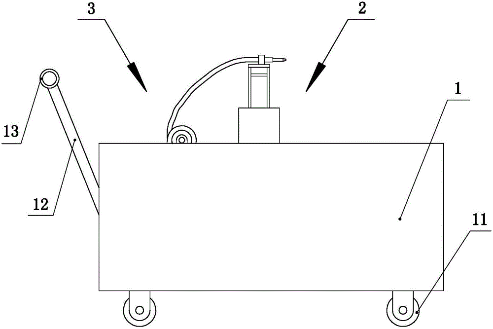
[0028] Such as Figure 1 to Figure 11 As shown, the present invention mainly includes a car body 1, a lift assembly 2, an oil supply assembly 3, a translation assembly and a rotation assembly, and the present invention will be described in detail below in conjunction with the accompanying drawings.

[0029] Such as figure 1 Shown, car body 1 is main body of the present invention, is provided with traveling wheel 11 at car body bottom, is provided with slanting bar 12 at car body rear side, is provided with handrail 13 at slanting bar free end, just can promote by holding handrail Bodywork.

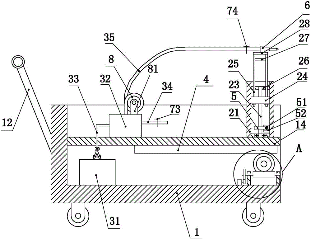
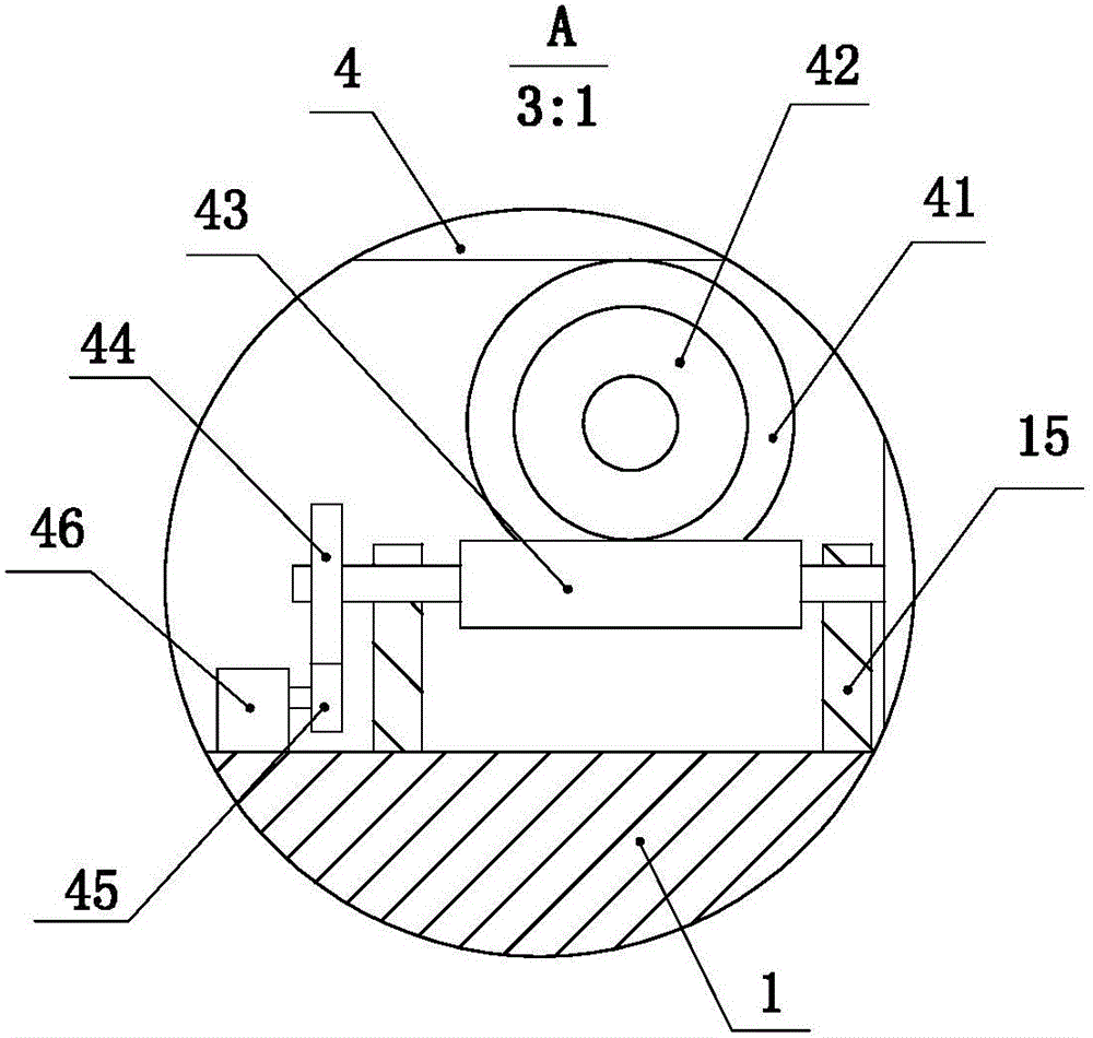
[0030] Such as figure 2 Shown, the car body is a hollow structure, and the inner cavity of the car body is provided with a dividing plate 14 placed horizontally, and a tooth bar 4 is slidably installed on the dividing plate. The lower side) extends out of the partition and is located below the partition. A bar-shaped hole is provided on the dividing plate, the upper side of the tooth ...


PUM


Abstract

A simple oil injecting device of a hydraulic mechanism is used for solving the problem that when oil is supplemented to the hydraulic mechanism, work efficiency is low. Traveling wheels and a handrail pushing a trolley body to travel are arranged on the trolley body, a partition plate is arranged in the inner cavity of the trolley body and provided with a lifting assembly in a sliding mode, and a horizontal movement assembly used for driving the lifting assembly to slide left and right in the horizontal plane is arranged on the trolley body. The lifting assembly comprises guiding components, a lead screw, a lead screw nut, supporting rods and a platform, wherein the lead screw is arranged among the guiding components, the lead screw nut is arranged in the middle of the lead screw, the supporting rods are fixed to the lead screw nut, and the platform is fixed to the tops of the supporting rods. A rotating assembly driving the lead screw to rotate is arranged on the partition plate. An oil supplying assembly is arranged on the trolley body and comprises a pumping and beating dual-purpose vacuum pump, an oil storing bag, an oil outflow pipe, an oil suction pipe and a gas pipe, and the oil suction pipe is arranged in an oil tank. By means of the simple oil injecting device, hydraulic oil in the oil tank can be fast pumped to the oil storing bag, oil injecting work is achieved, and work efficiency is high.

Description

technical field [0001] The invention relates to the technical field of hydraulic mechanisms, in particular to an oil injection device for injecting hydraulic oil into a hydraulic mechanism. Background technique [0002] The hydraulic mechanism has been widely used in the power system because of its excellent stability. However, due to the uneven quality of the mechanism manufacturing process and the difference in the sealing performance between the components, the mechanism often has oil leakage defects. When the oil pressure is too low , it is necessary to replenish oil to the mechanism. At present, the conventional method of replenishing oil is to use a syringe and a needle to suck out the hydraulic oil, and then inject it through the oil filling port of the hydraulic mechanism. The suction speed is too slow, and it is also relatively laborious, resulting in low work efficiency. For some large-scale equipment, the installation position of the hydraulic mechanism is relat...

Claims


Application Information

Patent Timeline
Patent Type & Authority Applications(China)
IPC IPC(8): B67D7/04B67D7/36B67D7/58
Inventor 李鑫李钦柱王洪贵刘珂朱洪波吕伟王雪岩王立王晓刚庄振福
Owner STATE GRID SHANDONG ELECTRIC POWER
Why Eureka
Try Eureka