Lattice structure steel bar connector and construction method of lattice structure steel bar connector

A steel connector and grid structure technology, which is applied to structural elements, building components, building structures, etc., can solve the problems of reduced strength, reduced connection strength, and increased construction difficulty, so as to achieve improved bending resistance and low weight. The effect of reducing and saving construction costs

Active Publication Date: 2015-10-07
SHANDONG ONE STAR CO NSTRUCTION TECH CO LTD
View PDF4 Cites 0 Cited by
  • Summary
  • Abstract
  • Description
  • Claims
  • Application Information

AI Technical Summary

Problems solved by technology

But when the tube wall is thicker, the diameter of the sleeve must be larger, and the grouting sleeve with a larger diameter cannot meet the national regulations in use. Concrete thickness requirements, this thickness is collectively referred to as the protective layer, the protective layer requirements for panels and walls is at least 15 mm, and the protective layer thickness of building beams or columns is at least 20 mm. The shortage of this grouting sleeve is: due to the The space is limited. When the position of the longitudinal reinforcement remains unchanged, the thickness of the protective layer between the outside of the grouting sleeve and the upper stirrup of the building component cannot meet the requirements of the national standard. Therefore, the longitudinal reinforcement in the concrete of the prefabricated component must be moved to the center of the interior. In order to increase the thickness of the protective layer between the steel bar connector and the building component stirrup, however, this will cause the longitudinal steel bar to be far away from the outer wall of the prefabricated part, resulting in a smaller ability to resist the bending moment of the wall, thus Reduce the mechanical performance of prefabricated components; at the same time, when the protective layer in the prefabricated component reaches the thicker requirement, it will cause the longitudinal reinforcement to move to the middle, affecting the ability of the prefabricated component to resist bending moments; when the prefabricated structural reinforcement moves inward , the ability to resist the bending moment becomes smaller. Therefore, the longitudinal reinforcement of the prefabricated component should be evenly distributed on both sides of the component and cannot move concentratedly in the middle. This requires the diameter of the grouting sleeve to be reduced to meet the requirements of the connection The distance of the longitudinal reinforcement moving to the middle of the prefabricated wall is as small as possible
However, the smaller the hole diameter of the grouting sleeve, the lower the grouting amount, resulting in reduced connection strength, and according to the national standard, the first horizontally distributed reinforcement of the shear wall is 50 mm from the bottom of the wall, but the height of the grouting sleeve is generally If it is larger than 100 mm, at least one horizontal stirrup must be provided outside the grouting sleeve located at the edge of the wall or at the connection part of the shear wall. The outer wall of the component is narrow, which cannot meet the requirements of the thickness of the concrete protective layer. Sometimes the steel bars are exposed, which leads to the corrosion of the steel bars, and the joint force of the steel bars and the concrete cannot be exerted, which seriously affects the building quality; in addition, the existing grouting sleeve is in use. , in order to meet the requirements of the national standard, it is necessary to add anti-cracking steel bars in the wall to prevent cracks in the concrete members after being stressed, resulting in increased construction costs and increased construction difficulty; the ring-shaped trapezoidal protrusions on the inner wall of the grouting sleeve are prone to fracture , leading to a substantial reduction in its strength

Method used


Image

  • Lattice structure steel bar connector and construction method of lattice structure steel bar connector
  • Lattice structure steel bar connector and construction method of lattice structure steel bar connector
  • Lattice structure steel bar connector and construction method of lattice structure steel bar connector

Examples


Embodiment Construction

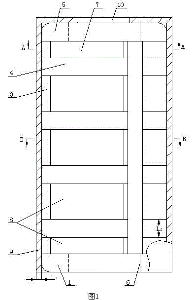
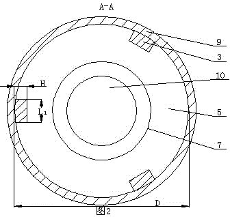
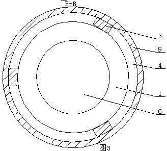
[0015] A grid structure steel bar connector according to the present invention includes a first support ring 1 and a second support ring 5, at least two longitudinal support ribs 3 are connected between the first support ring 1 and the second support ring 5, Multiple longitudinal support ribs 4 along 360 0 Distributed within the range, every two longitudinal support ribs 3 are connected with transverse arc-shaped support ribs 4, the transverse arc-shaped support ribs 4 are distributed along the height direction of the longitudinal support ribs 3, and at least three transverse arc-shaped support ribs 4 are distributed along the height direction of the longitudinal support ribs 3 , the outer wall of the transverse arc-shaped support rib 4 and the outer wall of the longitudinal support rib 3 are located in the same plane, the inner wall of the transverse arc-shaped support rib 4 and the inner wall of the longitudinal support rib 3 are located in the same plane, and a metal sleeve ...


PUM

PropertyMeasurementUnit
Wall thicknessaaaaaaaaaa

Abstract

The invention provides a lattice structure steel bar connector and a construction method of the lattice structure steel bar connector. The lattice structure steel bar connector comprises support rings, wherein two longitudinal support ribs are at least connected between the support rings; a plurality of longitudinal support ribs are distributed in a 360-degree range; a transverse arc-shaped support rib is connected between every two longitudinal support ribs; the transverse arc-shaped support ribs are distributed along the height direction of the longitudinal support ribs; at least three transverse arc-shaped support ribs are distributed along the height direction of the longitudinal support ribs; the outer wall of the transverse arc-shaped support ribs and the outer walls of longitudinal support ribs are positioned in the same plane; the inner walls of the transverse arc-shaped support ribs and the inner walls of the longitudinal support ribs are positioned in the same plane; a metal sleeve is arranged outside a space lattice-shaped tube body. A preparing method comprises the following steps that a cylindrical mold is taken and is put into a tube cavity; concrete is cast on the periphery of the cylindrical mold; the cylindrical mold is taken out; the construction is completed after the concrete is cast into a connecting hole. The lattice structure steel bar connector and the construction method of the lattice structure steel bar connector have the advantages that the structure of the steel bar connector in the prior art is thoroughly changed, so that the defects in the prior art are overcome.

Description

technical field [0001] The invention relates to a steel bar connection device used on building objects, which is a grid structure steel bar connector and a construction method thereof. Background technique [0002] Existing steel bar connector is commonly called as grouting sleeve, and it adopts thicker tube wall to increase the strength of grouting sleeve. But when the tube wall is thicker, the diameter of the sleeve must be larger, and the grouting sleeve with a larger diameter cannot meet the national regulations in use. Concrete thickness requirements, this thickness is collectively referred to as the protective layer, the protective layer requirements for panels and walls is at least 15 mm, and the protective layer thickness of building beams or columns is at least 20 mm. The shortage of this grouting sleeve is: due to the The space is limited. When the position of the longitudinal reinforcement remains unchanged, the thickness of the protective layer between the outsi...

Claims


Application Information

Patent Timeline
IPC IPC(8): E04C5/18E04G21/12
Inventor 张波
Owner SHANDONG ONE STAR CO NSTRUCTION TECH CO LTD
Why Eureka
Try Eureka