Optical fiber compound phase line joint box

A technology of optical fiber composite phase line and splice box, which is applied in the coupling of optical waveguide, fiber mechanical structure, etc., and can solve the problems of further maintenance hidden dangers, hidden dangers of maintenance or repair, and optical fiber broken at the end of stainless steel pipe, etc.

Inactive Publication Date: 2009-02-18
SHENZHEN SDG INFORMATION CO LTD
View PDF0 Cites 0 Cited by
  • Summary
  • Abstract
  • Description
  • Claims
  • Application Information

AI Technical Summary

Problems solved by technology

[0004] figure 2 The main defect of the splice box shown is that the stainless steel tube cannot be reserved in the splice box. Although the length of the optical fiber reserved in the splice box can meet the basic requirements of optical fiber fault repair and is sufficient to realize the fusion splicing of the optical fiber, due to the stainless steel tube The end fracture is very sharp, and the optical fiber may be broken at the end of the stainless steel tube during operation. As the cable outside the box body is charged during operation as mentioned above, it cannot be reserved due to safety requirements. At this time, There are no reserved optical fibers and stainless steel tubes. In order to repair the fault, it is necessary to strip the OPPC phase wire again to lead out the optical fiber. This requires re-adjusting the line or even replacing the line. Therefore, it is very troublesome to actually repair it. , and it also brings great hidden dangers to further maintenance in the future
Therefore, even if the joint box with the existing structure meets the requirements at the time of installation, the hidden dangers of maintenance or repair are very obvious

Method used


Image

  • Optical fiber compound phase line joint box
  • Optical fiber compound phase line joint box
  • Optical fiber compound phase line joint box

Examples


Embodiment Construction

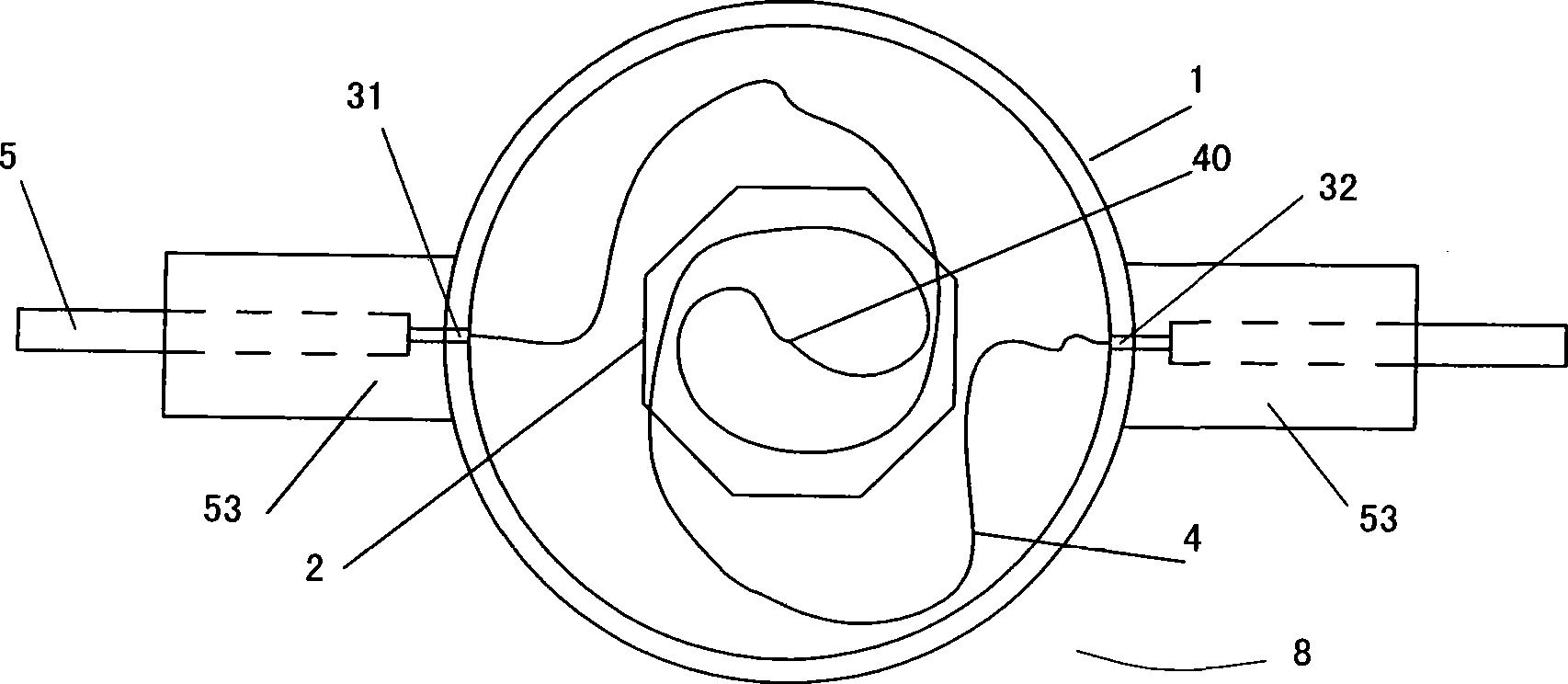
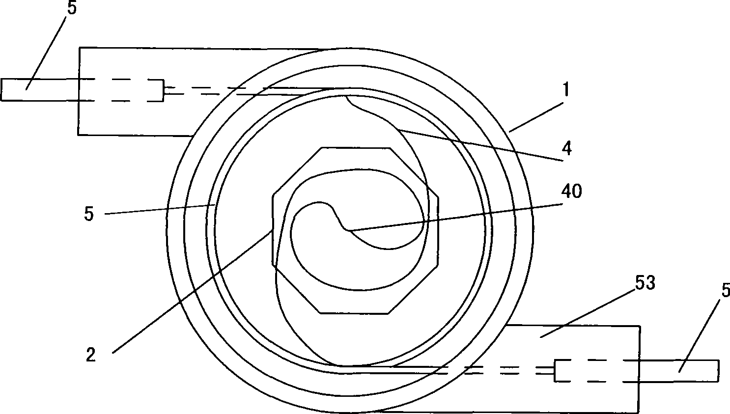
[0019] refer to image 3 , an embodiment of the optical fiber composite phase line splice box of the present invention, the splice box 8 includes a fiber tray 2 installed in the splice box box shell 1, and the box shell 1 is provided with two optical fibers for cladding The first cable inlet 31 and the second cable inlet 32 ​​introduced by the metal pipe 5 of 4 are respectively used for the metal pipe 5 to introduce or lead out the joint box 8; the reserved optical fiber is placed in the box shell 1 and placed in the The joints 40 of the two optical fibers are fused to each other, and the first cable entry hole 31 and the second cable entry hole 32 are both arranged on the side of the box shell 1 . The metal tube 5 covering the optical fiber 4 is currently mostly made of stainless steel. Of course, as long as the tube body made of other materials can meet the use or construction requirements, it should also be considered to have the same purpose, function and effect as the met...


PUM


Abstract

The invention discloses a splice closure for optical fiber composition phase conductor, which aims at solving the problem that the existing splice closure can not reserve long enough metal tube so as to cause the construction hidden trouble. The splice closure includes a fiber coiling tray which is arranged in the outer shell of the closure body, the closure body is provided with at least one cable inlet hole for the metal tube of the coating optical fiber to enter; the optical fiber is included in the closure body and is jointed by fusion, the cable inlet hole is arranged at the side part of the closure body, and the metal tube is included in the closure body in winding way; because the metal tube can be stored along the inner periphery of the splice closure in a sleek angle, so the long enough metal tube can be reserved in the closure body, the construction hidden trouble can be eliminated, and the maintenance and modification of the optical fiber composition conductor are convenient.

Description

technical field [0001] The invention relates to a connection device of an optical cable, in particular to an optical fiber joint device of an optical fiber composite phase line. Background technique [0002] The optical fiber composite phase line (OPPC for short) that appears to take into account the transmission of both optical and electrical signals is increasingly attracting the attention of power users. During the erection of the optical fiber composite phase line on the tower, such as figure 1 As shown, the optical cables in the phase line and between the optical cables and the guide optical cables need to be connected on the tower 90 . The usual connection method is: the optical fiber composite phase line 50 is erected on the tower 90 through insulators and fittings 91, and the metal tube 5 covering the optical fiber is separately drawn from the optical fiber composite phase wire 50, and is fixed on the pole tower 90 and insulated from the pole tower. The splicing box...

Claims


Application Information

Patent Timeline
IPC IPC(8): G02B6/38G02B6/44
Inventor 章飚
Owner SHENZHEN SDG INFORMATION CO LTD
Why Eureka
Try Eureka