

Oil separator for refrigerating system
A technology of oil separator and refrigeration system, which is applied in refrigerators, refrigeration components, refrigeration and liquefaction, etc. It can solve problems such as loud noise, and achieve the effect of avoiding noise and preventing liquid splashing
- Summary
- Abstract
- Description
- Claims
- Application Information
AI Technical Summary
Problems solved by technology
Method used
Image

Examples
Embodiment Construction
[0032] The present invention will be further described below in conjunction with the accompanying drawings and embodiments.
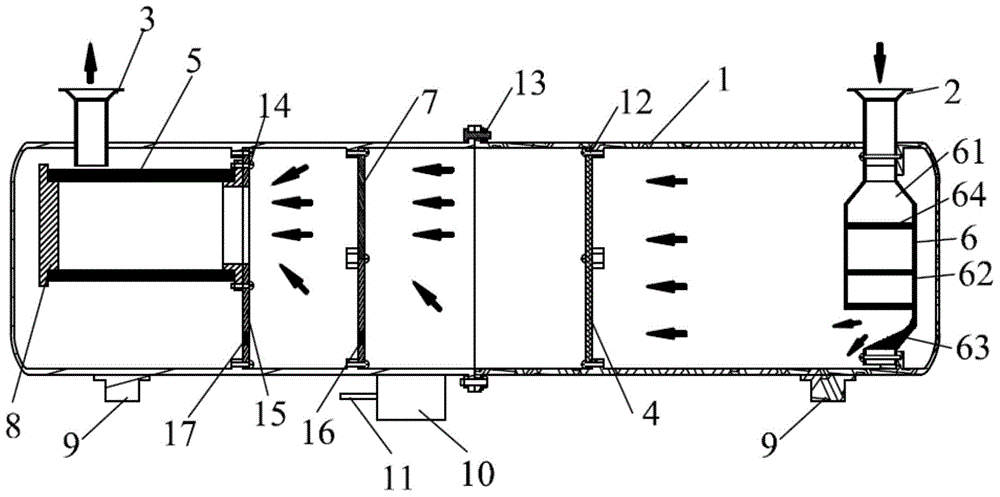
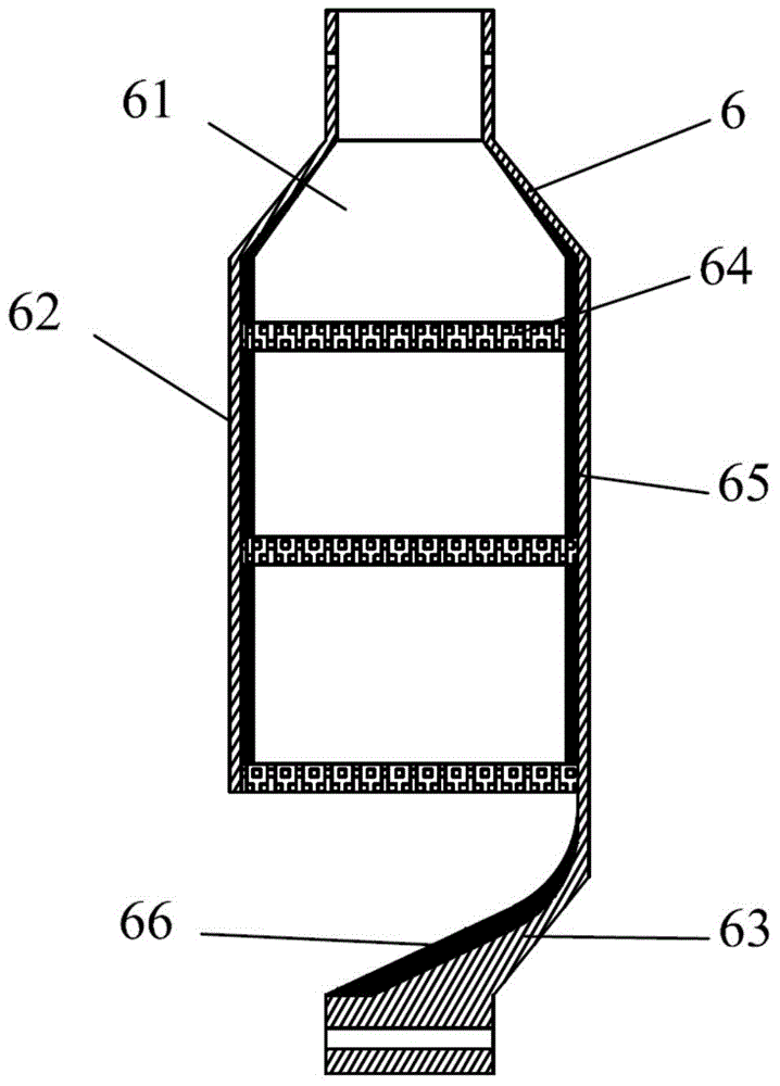
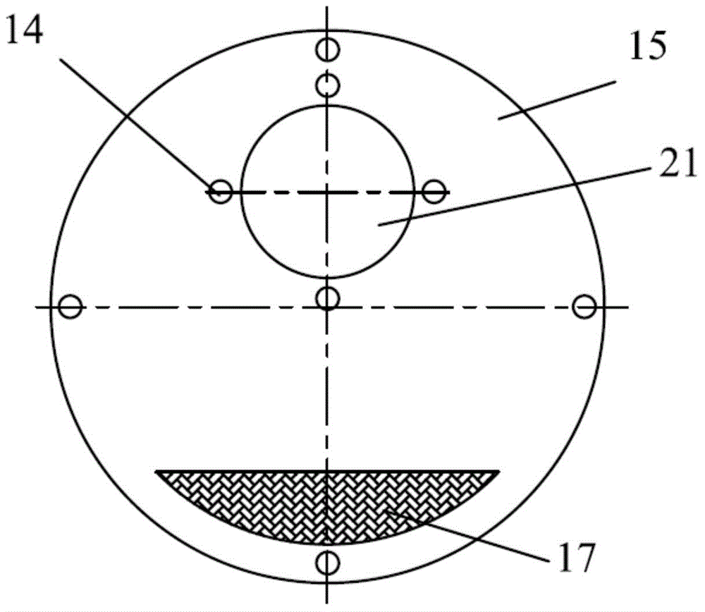
[0033] The first structural diagram of the embodiment of the oil separator for refrigeration system of the present invention can be found in figure 1 , an oil separator for a refrigeration system, comprising a cylinder body 1, an inlet pipe 2, and a discharge pipe 3, the inlet pipe 2 and the discharge pipe 3 are arranged at both ends of the cylinder body 1 and communicate with it, the axis of the inlet pipe 2 and the discharge pipe The axis of 3 is perpendicular to the axis of cylinder 1; in the direction from inlet pipe 2 to discharge pipe 3 in cylinder 1, there are first main filter 4, second main filter 7 and cylindrical structure filter element 5 in sequence, the first The main filter 4 is installed in the cylinder body 1 near the end of the inlet pipe 2 through the main filter fixing screw 12 and the inner wall of the cylinder body 1, and the secon...
PUM
| Property | Measurement | Unit |
|---|---|---|
| Thickness | aaaaa | aaaaa |
| Thickness | aaaaa | aaaaa |
| Thickness | aaaaa | aaaaa |
Abstract
Description
Claims
Application Information