Electric power drawer cabinet device capable of pushing out under automatic control

A drawer cabinet and drawer technology, applied in switchgear, pull-out switch cabinets, electrical components, etc., can solve problems such as inconvenient use, complex mechanical and electronic structures, and unfavorable maintenance of electrical cabinets, and achieve stable and balanced force and smooth operation. Simple and reliable, the effect of meeting the requirements of stability and reliability

Inactive Publication Date: 2015-10-07
嘉善泰迪电子商务有限公司
View PDF3 Cites 57 Cited by
  • Summary
  • Abstract
  • Description
  • Claims
  • Application Information

AI Technical Summary

Problems solved by technology

[0002] The drawer device of the existing electrical appliance cabinet often needs to be manually pulled out, which causes inconvenience to use
However, the use of power to realize the pulling movement can not flexibly realize the releasable manual removal of the drawer assembly, thus causing disadvantages to the maintenance wo

Method used


Image

  • Electric power drawer cabinet device capable of pushing out under automatic control
  • Electric power drawer cabinet device capable of pushing out under automatic control

Examples


Embodiment Construction

[0008] Combine below Figure 1-2 The present invention will be described in detail.

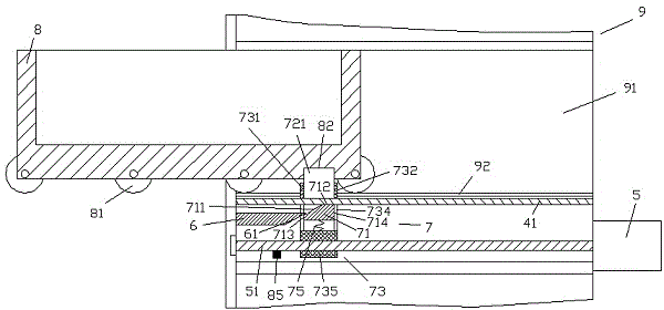
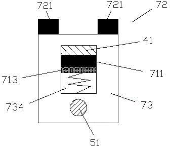
[0009] refer to Figure 1-2 , according to an embodiment, an automatic control push-out electric drawer device, including a frame body 9 and a drawer assembly 8, the lower sides of the drawer assembly 8 are provided with rollers 81 for accommodating the drawer on the frame body 9 The horizontal guide rail 92 on the lower side of the receiving cavity 91 of the component 8 cooperates so as to allow the drawer assembly 8 to enter and exit the receiving cavity 91 , and a horizontal slat is fixedly arranged on the lower side of the horizontal guiding rail 92 in the frame body 9 41, the horizontal slat 41 carries the driving slider assembly 7, and the driving slider assembly 7 includes two support arm plates 731, 732 arranged left and right and fixedly connected between the two support arm plates The U-shaped frame 73 composed of the bottom wall 735 of the U-shaped frame 73 and the telescopic sli...


PUM


Abstract

An electric power drawer cabinet device capable of pushing out under automatic control comprises a frame body (9) and a drawer assembly (8). Two sides of the lower portion of the drawer assembly (8) are provided with rollers (81) which are used for matching a transverse guide rail (92) at the lower side of an accommodating cavity (91), accommodating the drawer assembly (8), of the frame body (9), so that the drawer assembly (8) is allowed to be in and out of the accommodating cavity (91). A transverse batten (41) is disposed fixedly in the frame body (9) and at the lower side of the transverse guide rail (92). The transverse batten (41) carries a drive slider assembly (7). The drive slider assembly (7) comprises two support plates (731,732) disposed on left and right sides.

Description

technical field [0001] This application relates to the field of electric power, in particular to an electric power drawer device that is automatically controlled and rolled out. Background technique [0002] The drawer device of the existing electric appliance cabinet often needs to be manually pulled out, which causes inconvenience to use. However, the use of power to realize the pulling movement cannot flexibly realize the releasable manual removal of the drawer assembly, thereby causing disadvantages to the maintenance work of the electrical cabinet. However, if it is desired to realize such a method that can not only push and pull by power, but also facilitate manual removal of the drawer for maintenance, a more complex mechanical and electronic structure is required, which will have a negative impact on maintenance and equipment costs. Contents of the invention [0003] The object of the present invention is to provide an electric drawer device with automatic control...

Claims


Application Information

Patent Timeline
IPC IPC(8): H02B11/173
Inventor 不公告发明人
Owner 嘉善泰迪电子商务有限公司
Why Eureka
Try Eureka