
Low Output Voltage Ripple Discontinuous Mode Flyback Power Factor Correction Converter

A power factor correction, low output voltage technology, applied in output power conversion devices, regulating electrical variables, high-efficiency power electronic conversion, etc. The effect of volume, current spike reduction, and output voltage ripple reduction

Active Publication Date: 2017-08-04
NANJING UNIV OF SCI & TECH
View PDF6 Cites 0 Cited by
  • Summary
  • Abstract
  • Description
  • Claims
  • Application Information

AI Technical Summary

Problems solved by technology

[0004] The DCM Flyback converter is generally used in small and medium power applications. It is characterized by zero-current turn-on of the switch tube and no reverse recovery of the diode, but there are disadvantages such as high current peaks and large device stress.

Method used


Image

  • Low Output Voltage Ripple Discontinuous Mode Flyback Power Factor Correction Converter
  • Low Output Voltage Ripple Discontinuous Mode Flyback Power Factor Correction Converter
  • Low Output Voltage Ripple Discontinuous Mode Flyback Power Factor Correction Converter

Examples


Embodiment Construction

[0015] The present invention will be described in further detail below in conjunction with the accompanying drawings.

[0016] 1. Theoretical derivation:

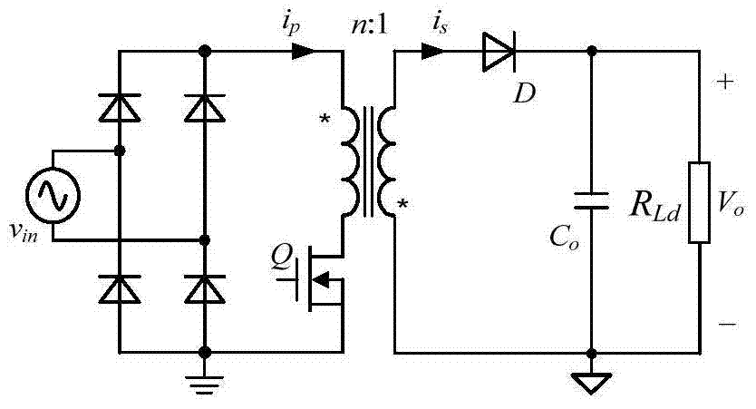
[0017] figure 1 It is the main power circuit of the Flyback converter.

[0018] Let the input AC voltage v in The expression is:

[0019] v in =V m sin ωt (1)

[0020] where V m is the peak value of the input voltage, ω=2πf line is the angular frequency of the input voltage, f line For the input voltage frequency, t is the time.

[0021] Then the rectified voltage v g for

[0022] v g =V m |sinωt| (2)

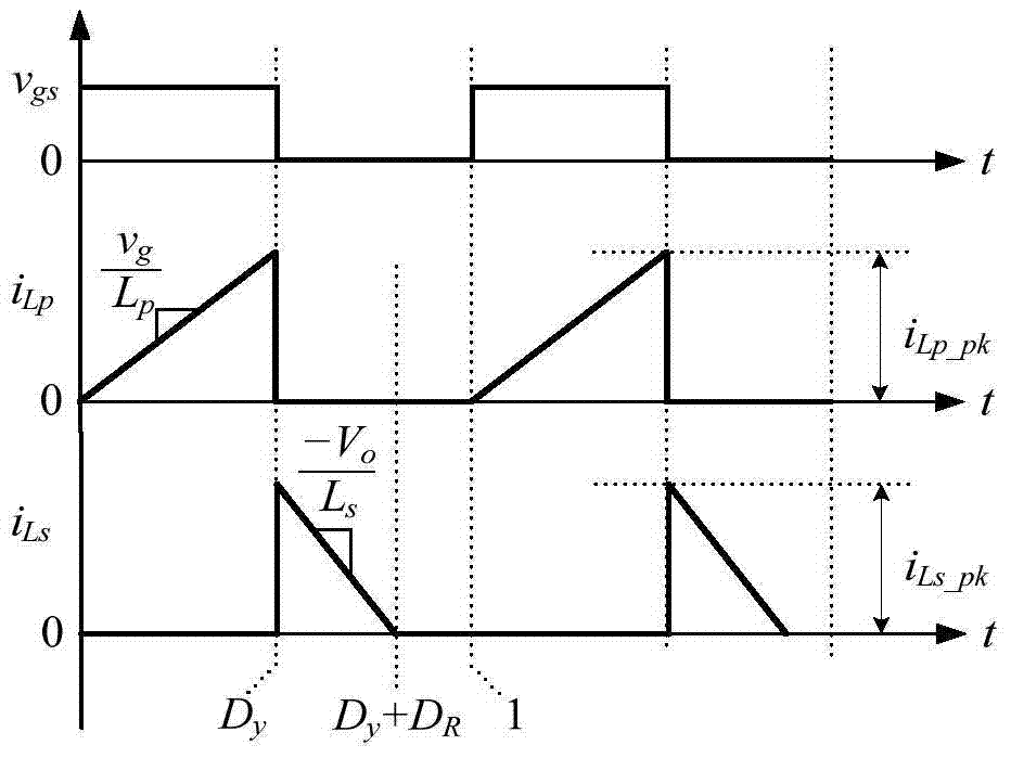
[0023] figure 2 When the Flyback converter works in DCM mode, the transformer primary and secondary inductor current waveforms are given in two switching cycles.

[0024] When the switch tube Q is turned on, the diode D is turned off, and the primary side inductance L p The voltage across it is v g , its current i p start with zero and start with v g / L p The slope rises linearly, the peak current i L...


PUM


Abstract

The invention discloses a low-output-voltage-ripple discontinuous-mode flyback power factor correction converter. The converter comprises a Flyback converter main power circuit, an output voltage feedback control circuit, a control drive circuit, and an input voltage feedforward circuit. The input voltage feedforward circuit comprises an input voltage sampling following circuit, an input voltage peak sampling circuit, a subtraction circuit, and a multiplying circuit. The output end of the input voltage sampling following circuit is connected with one input end of the subtraction circuit, and the output end of the input voltage peak sampling circuit is connected with the other input end of the subtraction circuit and one input end of the multiplying circuit. The output end of the subtraction circuit is connected with the other input end of the multiplying circuit. According to the invention, the input voltage feedforward circuit is introduced, thereby enabling the duty ratio of a switching tube to change regularly in a period of a working frequency, and finally achieving the output voltage ripple.

Description

technical field [0001] The invention belongs to the technical field of AC-DC converters in electric energy conversion devices, in particular to a low output voltage ripple discontinuous mode flyback power factor correction converter. Background technique [0002] A power factor correction (Power Factor Correction, PFC) converter can reduce input current harmonics and improve input power factor, and has been widely used. PFC converters are divided into active and passive methods. Compared with passive methods, active power factor correction has the advantages of high input power factor, small size, and low cost. [0003] The active PFC converter can adopt a variety of circuit extension and control methods, among which the Flyback converter is one of several basic converters. According to whether the inductor current is continuous, it can be divided into three operating modes: the inductor current continuous mode ( Continuous Current Mode, CCM), inductor current critical cont...

Claims


Application Information

Patent Timeline
Patent Type & Authority Patents(China)
IPC IPC(8): H02M3/335H02M1/42H02M1/14
CPCY02B70/10Y02P80/10
Inventor 姚凯毕晓鹏付晓勇周旭峰孟庆赛
Owner NANJING UNIV OF SCI & TECH
Learn More