Annular oscillator

A ring oscillator and delay unit technology, applied in the direction of automatic power control, electrical components, etc., can solve the problem of ring oscillator frequency offset, achieve stable oscillation frequency, reduce power supply voltage instability, and solve frequency offset Effect

Active Publication Date: 2015-10-07
北京中科芯蕊科技有限公司
View PDF5 Cites 1 Cited by
  • Summary
  • Abstract
  • Description
  • Claims
  • Application Information

AI Technical Summary

Problems solved by technology

[0005] The invention provides a ring oscillator, which can solve the problem that the ring oscillator is prone to

Method used


Image

  • Annular oscillator
  • Annular oscillator
  • Annular oscillator

Examples


Embodiment Construction

[0013] The following will clearly and completely describe the technical solutions in the embodiments of the present invention with reference to the accompanying drawings in the embodiments of the present invention. Obviously, the described embodiments are only some, not all, embodiments of the present invention. Based on the embodiments of the present invention, all other embodiments obtained by persons of ordinary skill in the art without making creative efforts belong to the protection scope of the present invention.

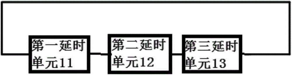
[0014] Such as figure 1 As shown, the embodiment of the present invention provides a ring oscillator, the ring oscillator includes a first delay unit 11, a second delay unit 12 and a third delay unit 13, the first delay unit 11 The output end is connected with the input end of the second delay unit 12, the output end of the second delay unit 12 is connected with the input end of the third delay unit 13, the third delay unit 13 The output end is connected to t...


PUM


Abstract

The invention discloses an annular oscillator, relating to the integrated circuit technology field. The invention solves the defect in the prior art the oscillation frequency is not stable. The annular oscillator disclosed by the invention is stable in the frequency and comprises a first time delay unit, a second time delay unit and a third time delay unit. The output terminal of the first time delay unit is connected to the input terminal of the second time-delay unit; the output terminal of the second time delay unit is connected to the input terminal of the third time delay unit. The output terminal of the third time delay unit is connected to the input terminal of the first time delay unit; the delaying time of the first time delay unit is in inverse proportion to power supply voltage of the annular oscillator; the delaying time of the second time delay unit is in direct proportion to the power supply voltage of the annular oscillator; and the delaying time of the third time delay unit is in inverse proportion to power supply voltage of the annular oscillator.

Description

technical field [0001] The invention relates to the technical field of integrated circuits, in particular to a ring oscillator. Background technique [0002] Oscillators are an essential part of electronic systems, providing accurate clock signals to chips. Ring oscillators are widely used because of their simple structure. Among them, CMOS ring oscillators made by CMOS (Complementary Metal Oxide Semiconductors) technology are generally composed of multi-stage standard CMOS inverters. The output end and the input end are connected end to end to form a ring. CMOS ring oscillators are widely used because of their simple structure, adjustable power consumption and high process portability. [0003] In the process of realizing the present invention, the inventor found that there are at least the following technical problems in the prior art: [0004] The oscillation frequency of the existing ring oscillator is usually unstable. In particular, the ring oscillator is easily aff...

Claims


Application Information

Patent Timeline
IPC IPC(8): H03L7/099
Inventor 乔树山谢正章赵慧冬
Owner 北京中科芯蕊科技有限公司
Why Eureka
Try Eureka