
Ink-sucking pipe equipped with stopper device for ink cartridge

A limit device and ink suction tube technology, which is applied in the field of ink suction tubes, can solve problems such as nozzle blockage or damage, poor image quality, and print nozzle damage.

Inactive Publication Date:
View PDF0 Cites 4 Cited by
  • Summary
  • Abstract
  • Description
  • Claims
  • Application Information

AI Technical Summary

Problems solved by technology

When the ink is placed for a long time, it is easy to produce sediment or aggregate into fine particles. These sediments or fine particles generated in the ink are easy to cause blockage or damage to the nozzle of the inkjet printer or inkjet printer, and also affect the nozzle of the inkjet printer. The quality of the printed image is adversely affected
Moreover, the ink suction tubes in these ink supply devices are all easily inserted into the bottom of the ink bottle, causing the ink to be sucked dry of the sediment in the bottle, which in turn causes damage to the print nozzle.

Method used


Image

  • Ink-sucking pipe equipped with stopper device for ink cartridge
  • Ink-sucking pipe equipped with stopper device for ink cartridge
  • Ink-sucking pipe equipped with stopper device for ink cartridge

Examples


Embodiment Construction

[0013] Embodiments of the present invention will now be described in conjunction with the accompanying drawings.

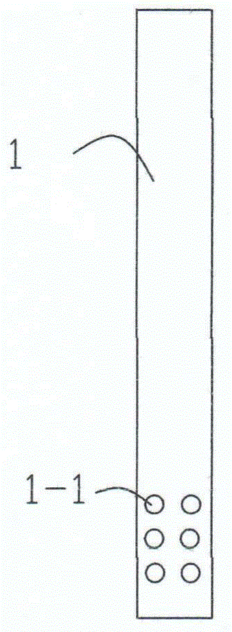
[0014] figure 1 It is a schematic diagram of the first preferred embodiment of the ink suction tube of the present invention. Such as figure 1 As shown, one end of the ink suction tube 1 is provided with a limiting mechanism 1-1.

[0015] Such as figure 1 As shown, the position-limiting mechanism is made up of several small holes 1-1. In this way, when the ink level drops to be flush with the uppermost aperture 1-1, the pressure inside and outside the ink suction tube reaches a balance, and the ink suction tube 1 can no longer suck ink, thereby ensuring that the ink will not be sucked dry.

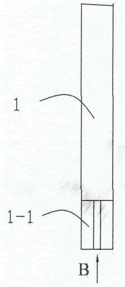
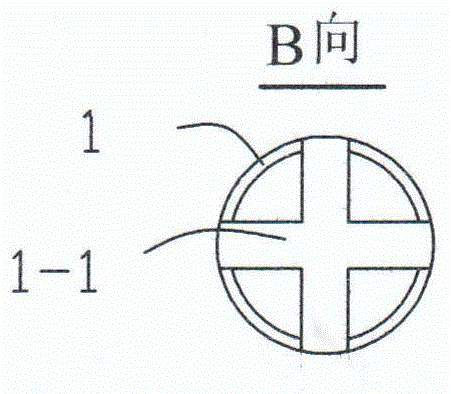
[0016] figure 2 and image 3 It is a schematic diagram of the third preferred embodiment of the ink suction tube of the present invention. This embodiment provides another structure of the limiting mechanism. Such as figure 2 and image 3 Shown, the position-limiti...


PUM


Abstract

The invention discloses an ink-sucking pipe equipped with a stopper device for an ink cartridge. The ink-sucking pipe equipped with a stopper device comprises an ink-sucking pipe. One end, extending into the ink cartridge, of the ink-sucking pipe is provided with the stopper device. By means of the stopper device, the ink-sucking pipe may suck the ink but cannot extend to the bottom of the ink cartridge. Therefore, the ink in the ink cartridge cannot be completely sucked such that a printing nozzle device is protected against damage.

Description

technical field [0001] The invention relates to a printing device, in particular to an ink suction tube for an ink bottle of an ink jet printer. Background technique [0002] In the prior art, inkjet printers or digital inkjet printers use an external ink supply system. Usually, an external ink supply system includes a container for holding ink and an ink suction tube for delivering ink. One end of the ink suction tube is connected to the nozzle of the printer. When the ink is placed for a long time, it is easy to produce sediment or aggregate into fine particles. These sediments or fine particles generated in the ink are easy to cause blockage or damage to the nozzle of the inkjet printer or inkjet printer, and also affect the nozzle of the inkjet printer. Printed image quality will be adversely affected. Moreover, the ink suction tubes in these ink supply devices are all easily inserted into the bottom of the ink bottle, causing the ink to be sucked dry of the sediment in...

Claims


Application Information

Patent Timeline
Patent Type & Authority Applications(China)
IPC IPC(8): B41J2/175
Inventor 周利荣周利军周利平
Learn More