Eureka AIR delivers breakthrough ideas for toughest innovation challenges, trusted by R&D personnel around the world.

Fan

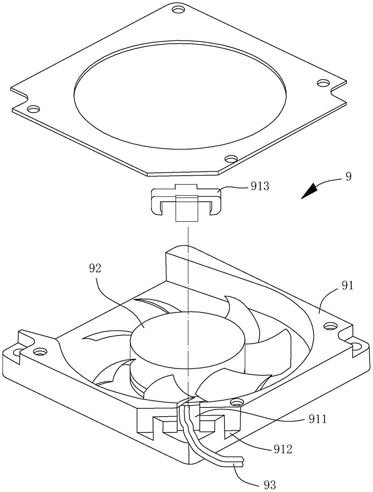
A fan and fan frame technology, which is applied in the field of fans provided with wireless power receiving coils, can solve the problems of increasing the structural complexity of the fan frame 91, the complex structure of the fan frame, and the short service life.

Active Publication Date: 2015-10-14
SUNONWEALTH ELECTRIC MACHINE IND
View PDF11 Cites 2 Cited by
  • Summary
  • Abstract
  • Description
  • Claims
  • Application Information

AI Technical Summary

Problems solved by technology

However, setting the wire groove 911, the buckle groove 912 or the buckle 913 on the fan frame 91 to limit and fix the structure of the power cord 93 will greatly increase the structural complexity of the fan frame 91, resulting in the It is difficult to mold the fan frame 91 and the manufacturing cost is correspondingly increased. Especially for small or micro fans, due to the small size of the fan frame, it is obviously not economical to add the above-mentioned wire slots 911, buckle slots 912 or buckle 913.
[0005] To sum up, the existing fan 9 is limited by relying on the power cord 93 to be electrically connected to an external power source, and has many disadvantages such as "short service life", "poor usability" and "complex structure of the fan frame". It is necessary to provide a further improved fan to solve the problems derived from the above-mentioned existing fan 9 provided with the power cord 93

Method used


Image

  • Fan
  • Fan
  • Fan

Examples


Embodiment Construction

[0068] In order to make the above-mentioned and other purposes, features and advantages of the present invention more obvious and easy to understand, the preferred embodiments of the present invention are specifically cited below, together with the accompanying drawings, and are described in detail as follows:

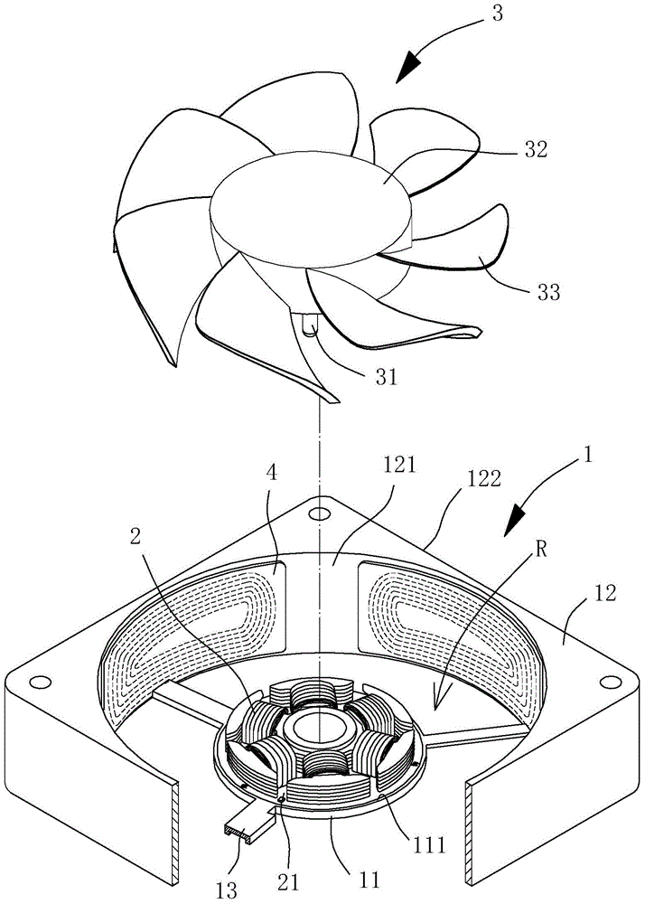
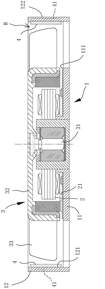
[0069] Please refer to figure 2 and 3 As shown, the fan according to the first embodiment of the present invention includes a fan frame 1 , a stator set 2 , a fan wheel 3 and a wireless power receiving coil 4 . The stator set 2 is disposed in the fan frame 1 ; the fan wheel 3 is rotatably combined with the stator set 2 ; and the wireless power receiving coil 4 is combined with the fan frame 1 . In this embodiment, the fan is an axial fan.

[0070] The fan frame 1 includes a base plate portion 11 and a surrounding wall portion 12 connected to each other. The surrounding wall portion 12 is arranged around the base plate portion 11, and the surrounding wall portion 12 ...


PUM


Abstract

Provided is a fan. A wireless power receiving coil is provided for receiving a wireless power signal for supplying power to the fan. The fan includes a fan frame including a substrate part and a ring wall part which are mutually connected and form accommodation space through encircling, a stator group arranged in the accommodation space, a fan wheel including an axis which is rotatablely combined with the stator group, and a wireless power receiving coil which is combined with the fan frame. And the wireless power receiving coil is electrically connected with the stator group.

Description

technical field [0001] The invention relates to a fan, especially a fan provided with a wireless power receiving coil. Background technique [0002] Please refer to figure 1 A conventional fan 9 is shown. The conventional fan 9 includes a fan frame 91 and a fan wheel 92. The fan wheel 92 is arranged in the fan frame 91, and the fan wheel 92 is driven by a motor to rotate. Accordingly, the fan wheel 92 must be electrically connected to a power cord 93, and the fan frame 91 forms a wire groove 911 for the power wire 93 to pass through, so that the power wire 93 can pass through the wire groove 911 to the The exterior of the existing fan 9 is electrically connected to an external power supply. One embodiment of the existing fan 9 has been disclosed in the invention patent case of Taiwan, China Announcement No. 443435 "Structural Improvement of Wire Buckle for Blower Fan". [0003] The above-mentioned existing fan 9 needs to use the power cord 93 to electrically connect to an...

Claims


Application Information

Patent Timeline
IPC IPC(8): F04D25/08F04D29/52H02J17/00
Inventor 林世航伍家进
Owner SUNONWEALTH ELECTRIC MACHINE IND
Why Eureka
Eureka Blog
Learn More