Fixed-dimensionality flying type multi-rotor aircraft and flying control method

A multi-rotor aircraft and flight control technology, applied in the field of unmanned aerial vehicles, can solve problems such as not being able to solve specific needs

Inactive Publication Date: 2015-10-14
杨珊珊
View PDF12 Cites 16 Cited by
  • Summary
  • Abstract
  • Description
  • Claims
  • Application Information

AI Technical Summary

Problems solved by technology

[0021] Since this method focuses on the completion of aeronautical geophysical prospecting tasks, the flight height control in this method is still a method for specific situations, which comprehensively applies the data of altitude and radio altitude. This method is only applicable to The aeronautical geophysical prospecting task proposed by this patent cannot solve the specific needs raised by this application

Method used


Image

  • Fixed-dimensionality flying type multi-rotor aircraft and flying control method
  • Fixed-dimensionality flying type multi-rotor aircraft and flying control method
  • Fixed-dimensionality flying type multi-rotor aircraft and flying control method

Examples


Embodiment 1

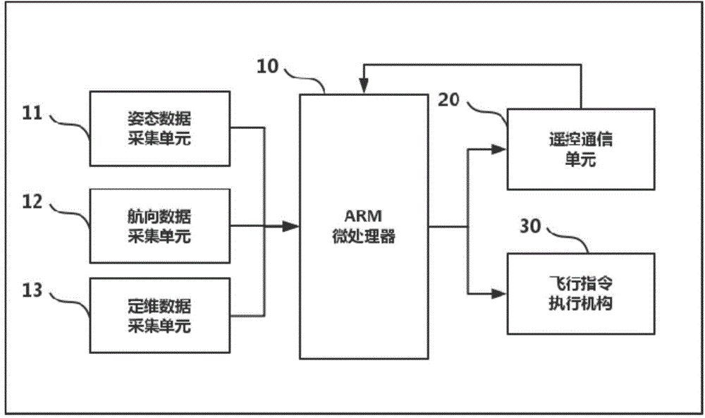
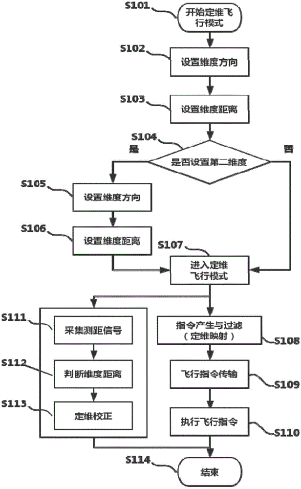
[0049] figure 1 A schematic diagram of the frame structure of the flight control part of the multi-rotor unmanned aerial vehicle according to Embodiment 1 of the present invention is shown. Such as figure 1 As shown, the flight control part includes a microprocessor 10 for completing all flight control signal processing (this application typically takes an ARM microprocessor as an example), and this processor can complete intelligent data processing with a small volume , the microprocessor 10 acquires the data relevant to the flight of the unmanned aerial vehicle from a plurality of data acquisition units, which may commonly include an attitude data acquisition unit 11 about the flight attitude, and a heading data acquisition unit 12 about the flight direction, especially according to The specific needs of the present application also have a fixed-dimensional data acquisition unit 13 for collecting data related to fixed-dimensional control. The fixed-dimensional data acquisit...

Embodiment 2

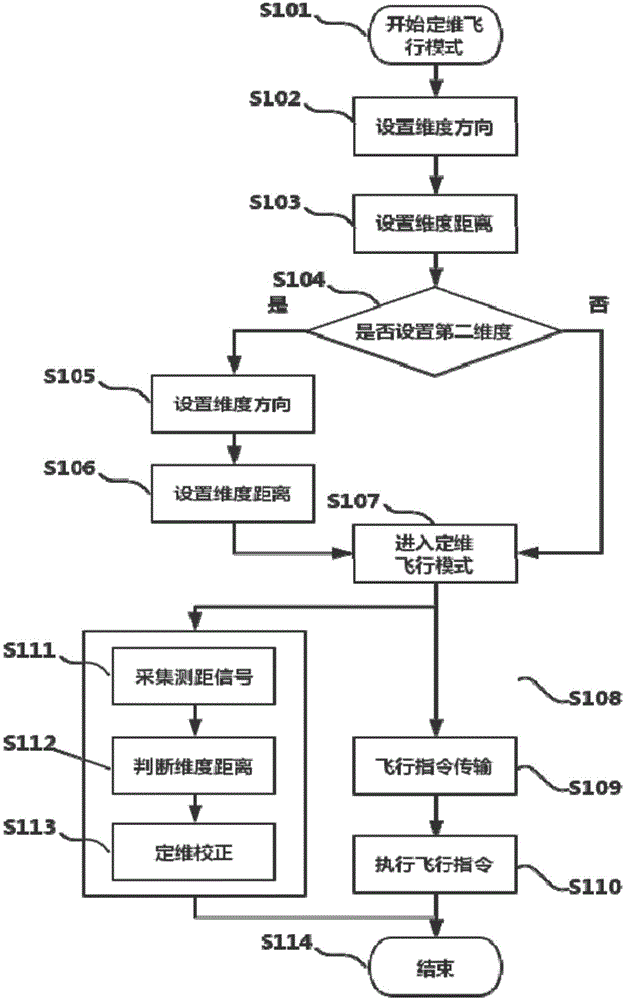
[0091] image 3 A flow chart of a flight control method for a multi-rotor unmanned aerial vehicle according to Embodiment 2 of the present invention is shown. The steps of the flow chart are the same as those in Embodiment 1 of the present invention, and will not be repeated here. Here, the flight mode steps with differences are mainly described as follows:

[0092] In Embodiment 2 of the present invention, step S108 in the original Embodiment 1 is omitted. Although the flight control command from the remote control terminal / ground station may cause the unmanned aerial vehicle to be displaced in the dimension of the intended fixed distance, this This kind of displacement can be corrected by fixed-dimensional correction implemented at the same time.

[0093] In other words, the unmanned aerial vehicle can accept and execute the flight instructions from the remote terminal through its flight controller, but the dimension correction command executed at the same time can eliminat...

Embodiment 3

[0096] Figure 4 A schematic diagram of a frame structure of a multi-rotor unmanned aerial vehicle in the prior art is shown. A common multi-rotor unmanned aerial vehicle basically includes a flight controller 30, a power supply 40, a motor drive unit 50, and a remote control signal receiving unit 60, wherein the flight controller 30 is responsible for the flight control of the unmanned aerial vehicle as the center, and the power supply 40 is all The components of the unmanned aerial vehicle provide power, and the motor drive unit 50 generally includes a rotor driven by a motor, and the output power of the motor can be adjusted through an electronic governor. The electronic governor implements different levels of drive to different rotors, which can enable the unmanned aerial vehicle to complete free flight within the space range. In addition, the flight controller 30 is used as the main controller in order to effectively control and manage the flight process of the unmanned ...


PUM


Abstract

The invention discloses a multi-rotor unmanned aircraft and a flying control method thereof. The unmanned aircraft can be preset and controlled to fly at a specific distance from a reference target in one dimension. In this way, the unmanned aircraft is manipulated to move. Therefore, the flight experience of a user is ensured, while the operation difficulty of the user is simplified at the same time. Meanwhile, the user can be transitionally adapted to the unmanned aircraft. In some special cases, the flight control complexity is reduced, and more complicated flight missions can be realized simply. Moreover, the fixed-dimensionality flying type multi-rotor aircraft is excellent in flight display effect.

Description

technical field [0001] The present application relates to the field of unmanned aerial vehicles, in particular to a flight control method of a multi-rotor unmanned aerial vehicle and a multi-rotor unmanned aerial vehicle to which the flight control method is applied. Background technique [0002] Unmanned aerial vehicles have a wide range of applications in aerial photography, flight performances, disaster prevention and rescue, scientific investigation and other fields. Especially with the rapid development of electronic technology, small and micro drones have made significant breakthroughs in remote control, battery life, and flight quality, and have become the focus of attention in the general aviation field that has emerged in recent years. development prospects. [0003] At present, unmanned aerial vehicles, especially four-axis multi-rotor unmanned aerial vehicles, have begun to enter the consumer market. Compared with traditional fixed-wing aircraft, multi-rotor airc...

Claims


Application Information

Patent Timeline
Patent Type & Authority Applications(China)
IPC IPC(8): G05D1/10
Inventor 杨珊珊
Owner 杨珊珊
Why Eureka
Try Eureka