
Bidirectional switching-off DC circuit breaker and switching-off method thereof

A DC circuit breaker and branch circuit technology, applied in the direction of emergency protection circuit devices, electrical components, etc., can solve the problems of high rated current loss, poor fracture insulation recovery, and low rated current loss

Pending Publication Date: 2019-05-03
XI AN JIAOTONG UNIV
View PDF0 Cites 24 Cited by
  • Summary
  • Abstract
  • Description
  • Claims
  • Application Information

AI Technical Summary

Problems solved by technology

[0002] The DC circuit breaker is one of the core equipment to ensure the safe and reliable operation of the DC distribution network. At present, the solid-state DC circuit breaker based on the solid-state switch transfer breaking scheme has good fracture recovery characteristics after current transfer, and the breaking speed of the full current range is fast. However, due to the large The power electronic devices are connected in series in the rated current circuit, the rated current loss is high, and the breaking capacity is limited; the mechanical DC circuit breaker based on the pre-charge capacitor transfer scheme has low rated current loss and strong breaking capacity, but the small current Long breaking time and poor fracture insulation recovery

Method used


Image

  • Bidirectional switching-off DC circuit breaker and switching-off method thereof
  • Bidirectional switching-off DC circuit breaker and switching-off method thereof
  • Bidirectional switching-off DC circuit breaker and switching-off method thereof

Examples


Embodiment Construction

[0042] The following will refer to the attached Figure 1 to Figure 12(d) Specific examples of the present invention are described in more detail. Although specific embodiments of the invention are shown in the drawings, it should be understood that the invention may be embodied in various forms and is not limited to the embodiments set forth herein. Rather, these embodiments are provided for more thorough understanding of the present invention and to fully convey the scope of the present invention to those skilled in the art.

[0043] It should be noted that certain terms are used in the specification and claims to refer to specific components. Those skilled in the art should understand that they may use different terms to refer to the same component. The specification and claims do not use differences in nouns as a way of distinguishing components, but use differences in functions of components as a criterion for distinguishing. "Includes" or "comprises" mentioned through...


PUM


Abstract

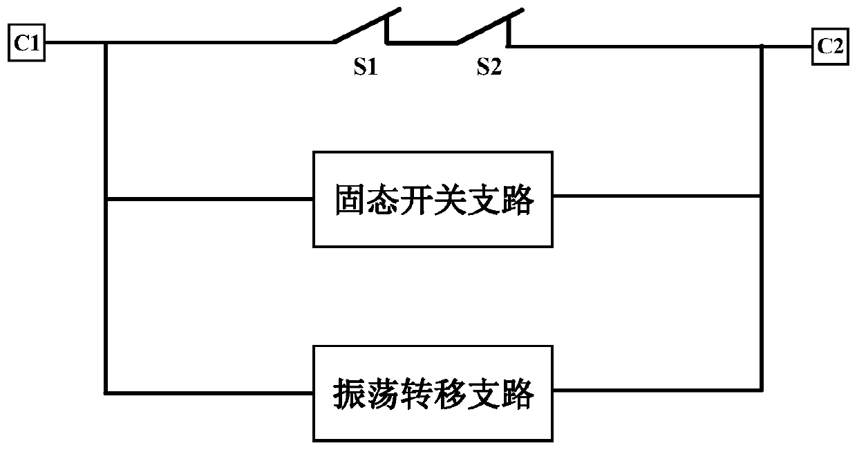
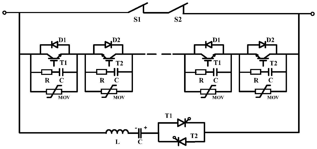
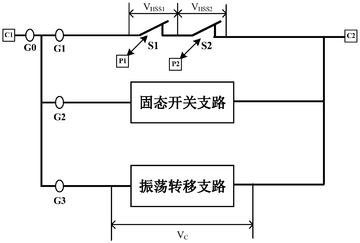
The invention discloses a bidirectional switching-off DC circuit breaker and a switching-off method. The circuit comprises a main current loop, a solid-state switch branch, an oscillation transfer branch, a control system, a wire outlet terminal C1 and a wire outlet terminal C2. The main current loop, the solid-state switch branch and the oscillation transfer branch are connected in parallel and are led out through the wire outlet terminals C1 and C2. A diode D1 in a solid-state switch assembly is in anti-parallel connection with the two ends of a full-control power semiconductor device T1. Acapacitor C and a resistor R are connected in series and then connected with the MOV in parallel, and then is connected in parallel with two ends of T1. A diode D2 is in anti-parallel connection withthe two ends of a full-control power semiconductor device T2. The capacitor C and the resistor R are connected in series and then connected with the MOV in parallel, and then are connected in parallelwith two ends of T2, and T1 and T2 are in anti-series connection. Positive electrodes and negative electrodes of the semi-controlled power semiconductors T1 and T2 are reversely connected in series.One end of an inductor is connected with the positive electrode of the T1, the other end of the inductor is connected with the other end of the capacitor, and the other end of the capacitor is connected with the wire outlet terminal C1 which is connected with the negative electrode of the T1.

Description

technical field [0001] The invention relates to a bidirectional breaking DC circuit breaker and a breaking method thereof, in particular to forced current transfer by an over-arc voltage, changing the timing sequence of a power semiconductor device triggering a solid-state switch branch and an oscillation transfer branch to realize shutting off different flow directions function of the current. Background technique [0002] The DC circuit breaker is one of the core equipment to ensure the safe and reliable operation of the DC distribution network. At present, the solid-state DC circuit breaker based on the solid-state switch transfer breaking scheme has good fracture recovery characteristics after current transfer, and the breaking speed of the full current range is fast. However, due to the large The power electronic devices are connected in series in the rated current circuit, the rated current loss is high, and the breaking capacity is limited; the mechanical DC circuit b...

Claims


Application Information

Patent Timeline
IPC IPC(8): H02H7/26
Inventor 吴翊吴益飞杨飞荣命哲纽春萍肖宇
Owner XI AN JIAOTONG UNIV
Learn More