Variable-speed rotating LED display system and method for displaying the same

A display system and variable technology, applied in static indicators, graphic image conversion, image data processing and other directions, can solve the problems of inability to display images stably, inflexible system control, user inconvenience, etc., to save LED lights and increase freedom Sex, brightness adjustable effect

Active Publication Date: 2015-10-14
SHENZHEN MAKERSCOPE TECH CO LTD
View PDF17 Cites 19 Cited by
  • Summary
  • Abstract
  • Description
  • Claims
  • Application Information

AI Technical Summary

Problems solved by technology

[0003] Patent Document 1 (Chinese Invention Patent Publication No. CN1750069A) "Persistence of Vision Display System and Method for Realizing Display thereof" is characterized in that a PC is used to send the content to be displayed, and the rotation of the display screen needs to be driven by a motor, and it is fixed on the On a specific platform, making the entire system control inflexible
[0004] The "LED Graphic Display System" of Patent Document 2 (Chinese Invention Patent Publication No. CN101923815A) is characterized in that it utilizes the principle of people's persistence of vision and uses a luminous bar to make the LED display a certain graphic effect, but only in the luminous bar It has a better effect when rotating at a constant speed, and the graphic storage unit needs to be customized or updated, which brings inconvenience to users
[0005] Patent Document 3 (Chinese Invention Patent Publication No. CN104463781A) "Method for controlling POV display device to display images and method for displaying animation", which only has a good effect when rotating at a constant speed, and cannot display images stably under variable speed conditions. And when displaying gif, it is necessary to keep the bluetooth connection status all the time, which brings inconvenience to the user

Method used


Image

  • Variable-speed rotating LED display system and method for displaying the same
  • Variable-speed rotating LED display system and method for displaying the same
  • Variable-speed rotating LED display system and method for displaying the same

Examples


Embodiment Construction

[0031] The present invention will be further described below in conjunction with the accompanying drawings and specific embodiments.

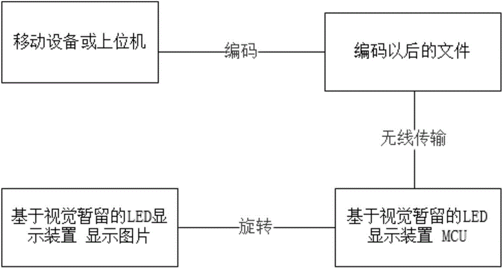
[0032] as attached figure 1 As shown, the variable-speed rotating LED display system of the present invention includes a host computer (which can be a mobile terminal device, such as a PDA, a mobile phone, an iPad, or a PC), an LED display device based on persistence of vision; the LED display The device includes MCU unit, position sensor, wireless receiving unit, rotating arm, LED light and rotating motor. The host computer is used to perform encoding preprocessing on any picture, animation (mainly GIF format) and video to be displayed within the display range of the LED display device, and obtain the encoded file, which is stored on the host computer; Then, the encoded file is transmitted to the LED display device in a wireless communication mode. The wireless receiving unit of the LED display device is used to receive coded data and store ...


PUM


Abstract

The invention provides a variable-speed rotating LED display system which comprises an upper computer and an LED display device based on vision duration. The upper computer is used for performing coding preprocessing on to-be-displayed contents in the display range of the display device, obtaining files having been encoded, and transmitting the files having been encoded to the display device in a wireless communication mode. A position sensor of the display device is used for calculating the position posture of a rotating arm, obtaining the accurate posture angle of the rotating arm and transmitting the accurate posture angle to an MCU of the display device. The MCU is used for controlling an LED lamp on the rotating arm in rotating according to the real-time posture angle so that the display device can display brightness-adjustable contents. The variable-speed rotating LED display system greatly improves freedom between the upper computer and the LED display device, meets users' requirements and experience and provides a new development direction for the application of the LED display device.

Description

technical field [0001] The invention belongs to the technical field of information display, in particular to a variable-speed rotating LED display system. Background technique [0002] With the rapid development of my country's electronic technology and the improvement of people's living standards, people's pursuit of entertainment and outdoor sports has become higher, which has brought new opportunities to the LED display device production industry, and it is also very huge. challenge. Therefore, the LED display device industry is constantly pursuing modernization and intelligence in the field, and strives to increase the dynamics of the LED display device and strive to achieve the movement of the screen. Due to the wide range of application fields of LED display devices, people's pursuit of beauty is increasing, and my country's vigorous advocacy of establishing a resource-saving and environment-friendly society and the cultivation of people's innovation ability, therefore...

Claims


Application Information

Patent Timeline
Patent Type & Authority Applications(China)
IPC IPC(8): G09F9/33G06T3/00G06T3/40
CPCG06T3/00G06T3/40G09F9/33G09G3/005
Inventor 刘兴华肖为栋刘志勇
Owner SHENZHEN MAKERSCOPE TECH CO LTD
Why Eureka
Try Eureka