Automatic dimming lamp circuit

An automatic dimming and lighting technology, which is applied in the direction of electric lamp circuit layout, light source, electric light source, etc., can solve the problems of manual adjustment, high power consumption of dimming circuit, etc., and achieve the effect of saving labor intensity

Inactive Publication Date: 2015-10-14
吴燕珊
View PDF4 Cites 4 Cited by
  • Summary
  • Abstract
  • Description
  • Claims
  • Application Information

AI Technical Summary

Problems solved by technology

It can solve the problems of large power consumption and manual adjustment of the dimming circuit in the prior art

Method used


Image

  • Automatic dimming lamp circuit
  • Automatic dimming lamp circuit

Examples


Embodiment Construction

[0026] The following will clearly and completely describe the technical solutions in the embodiments of the present invention with reference to the accompanying drawings in the embodiments of the present invention. Obviously, the described embodiments are only some, not all, embodiments of the present invention.

[0027] Based on the embodiments of the present invention, other embodiments obtained by persons of ordinary skill in the art without making creative efforts all belong to the protection scope of the present invention.

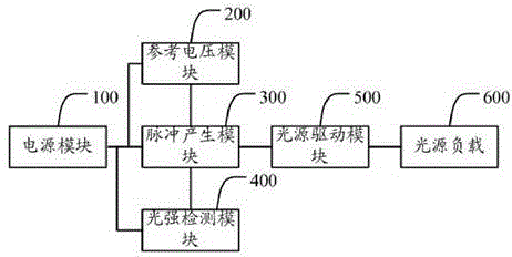
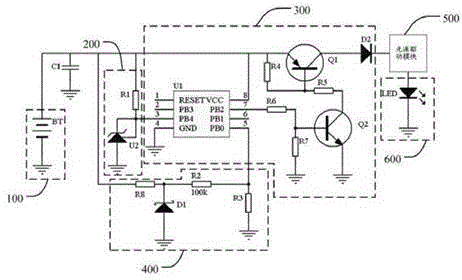
[0028] See figure 1 , is a schematic structural diagram of an automatic dimming lamp circuit according to an embodiment of the present invention, the dimming control circuit includes:

[0029] The power supply module 100, the reference voltage module 200, the pulse generation module 300, the light intensity detection module 400, the light source driving module 500 and the light source load 600, the power supply module 100 is respectively connected wit...


PUM


Abstract

The embodiment of the invention discloses an automatic dimming lamp circuit comprising a pulse generating module connected with a power module and a light source driving module, a reference voltage module connected with the power module and the pulse generating module, and a light intensity detection module connected with the power module and the pulse generating module. The automatic dimming lamp circuit may adjust the light intensity of the light source according to the light intensity of external environment and is simple, reliable, and high efficient in energy.

Description

technical field [0001] The invention relates to a control circuit and device of a light source. Background technique [0002] With the development of science and technology, people's requirements for energy saving are getting higher and higher. The existing dimming control circuit uses a potentiometer to adjust the voltage and current of the light source to adjust the luminous intensity of the light source. Although this dimming method is simple, the potentiometer needs to consume extra power in the circuit, which cannot meet the requirements of energy saving; Or use PWM (Pulse Width Modulation, pulse width modulation) to adjust the duty cycle of the pulse signal to control the power input to the light source, thereby controlling the luminous intensity of the light source. Usually, several levels of gears are set to manually adjust the power of the light source. Luminous intensity, but this method requires artificial adjustment of luminous intensity, which cannot adapt well...

Claims


Application Information

Patent Timeline
Patent Type & Authority Applications(China)
IPC IPC(8): H05B37/02
Inventor 吴燕珊
Owner 吴燕珊
Why Eureka
Try Eureka