Scanner of optical source device using self-light-focusing effect

A scanner and optical scanning technology, applied in the field of scanners, can solve the problem of not meeting the development requirements of high-speed scanning scanners, and achieve the effect of increasing the luminous flux density and improving the uniformity

Inactive Publication Date: 2004-01-28
UMAX DATA SYST
View PDF0 Cites 0 Cited by
  • Summary
  • Abstract
  • Description
  • Claims
  • Application Information

AI Technical Summary

Problems solved by technology

However, the light source device 130 with this structure does not meet the development requirements of scanners with high-speed scanning and low exposure time due to its light scattering characteristics.

Method used


Image

  • Scanner of optical source device using self-light-focusing effect
  • Scanner of optical source device using self-light-focusing effect
  • Scanner of optical source device using self-light-focusing effect

Examples


Embodiment Construction

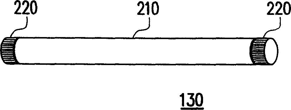
[0046] Please refer to image 3 As shown, it is a schematic cross-sectional view of a light source device according to a preferred embodiment of the present invention. Depend on image 3 It can be seen from the figure that the light source device 300 has a self-light-collecting effect in order to collect the scattered light into a light beam and then emit it to the document to be scanned, so it still has figure 2 In addition to the lamp tube 210, the electrodes 220 on both sides, the fluorescent substance (not shown) coated on the inner wall of the lamp tube 360, and the mercury vapor and some rare gases (not shown) sealed in the lamp tube 210, there are also A layer of total reflection material 320 is coated on the outer wall 350 of the lamp tube, and an opening 330 is left on the side facing the document (not shown) for emitting the collected light beam 340 . Of course, those skilled in the art can also apply it on the inner wall 360 of the lamp tube.

[0047] When volta...


PUM


Abstract

In the invention, total reflection material is coated on tube wall of lamp or the tube wall is processed as convergent lens type in order to make light source itself possess effect of collecting light. Thus, with scattered light being collected, the collected light emits out to the line on the file to be scanned, in order to raise luminous flux density. The invented light source also can be as the assistant light source located in two sides of the main source as well as a control circuit able to adjust luminous intensity can be added so as to increase luminous flux density at two sides, also improve uniformity of luminous flux at photoreceptor.

Description

technical field [0001] The invention relates to a scanner, and in particular to a scanner using a light source device with self-light collection effect. Background technique [0002] In recent years, with the great progress of digital technology, coupled with the high development of Internet and multimedia technology, many images hope to be converted into digital images for processing. Therefore, a digital camera (Digital Camera, DC) is used to directly capture the physical scene, and an optical scanner (Optical Scanner) is used to capture images on documents or pictures, and convert them into digital image data for output to facilitate Users perform operations such as display, recognition (OCR), editing, storage, and output of digital image files on computers or other electronic products. [0003] If the distinction is made according to the input method of the document image, the optical scanner can be divided into a palm scanner, a sheet feed scanner (Sheet Feed Scanner),...

Claims


Application Information

Patent Timeline
Patent Type & Authority Applications(China)
IPC IPC(8): G02B26/08G06V30/144
Inventor 张庆琳
Owner UMAX DATA SYST
Why Eureka
Try Eureka