An LED light emitting device for increasing luminous flux density

A light-emitting device and luminous flux technology, which is applied in the direction of electrical components, electric solid-state devices, circuits, etc., can solve the problems of low power, the inability of LED light-emitting devices to be actually put into use, and the inability to increase heat dissipation performance and power synchronously, so as to achieve the goal of increasing density Effect

Inactive Publication Date: 2019-01-11
厦门吉来特光电有限公司
View PDF0 Cites 0 Cited by
  • Summary
  • Abstract
  • Description
  • Claims
  • Application Information

AI Technical Summary

Problems solved by technology

[0002] Every time the power of the LED lighting device, especially the increase in the luminous flux per unit area (that is, the optical density), must be simultaneously optimized for the difficulty of heat dissipation, if the heat dissipation performance of the LED grains in the LED lighting device cannot be compared with If the power is increased synchronously, then the entire

Method used


Image

  • An LED light emitting device for increasing luminous flux density
  • An LED light emitting device for increasing luminous flux density
  • An LED light emitting device for increasing luminous flux density

Examples


Embodiment Construction

[0048] In order to further explain the technical solution of the present invention, the present invention will be described in detail below through specific examples.

[0049] like Figure 1 to Figure 17 As shown, it is a demonstration of various specific embodiments of an LED lighting device with improved luminous flux density related to the present invention.

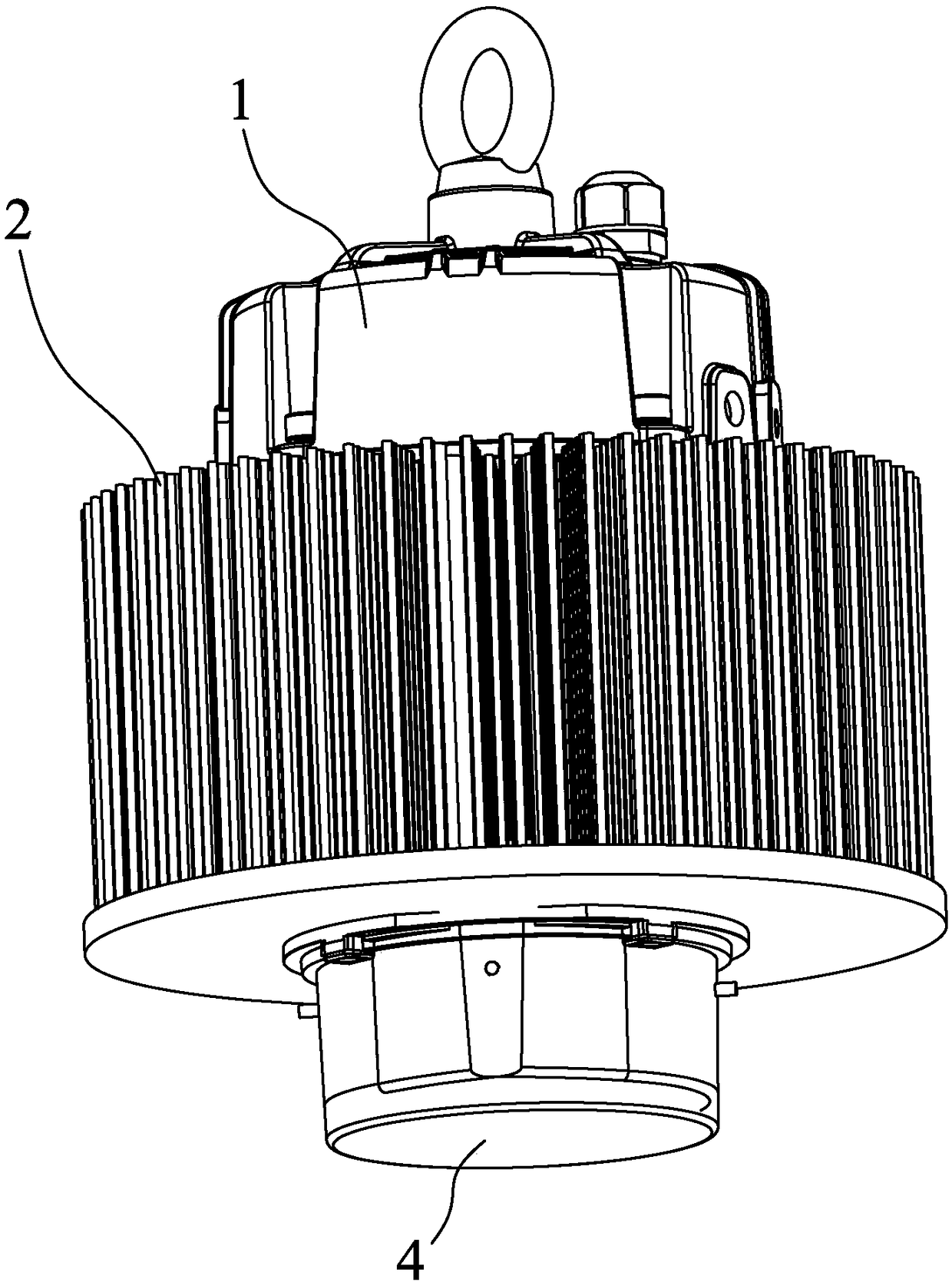
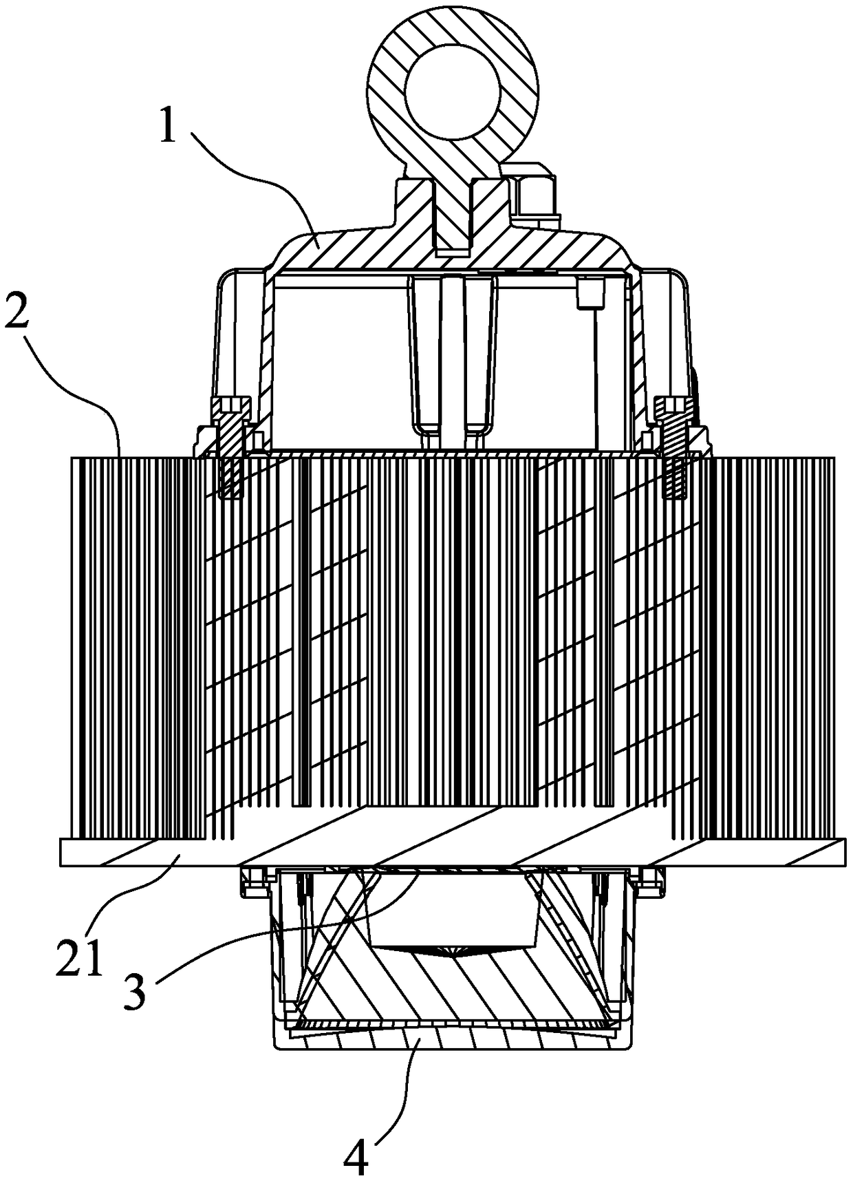
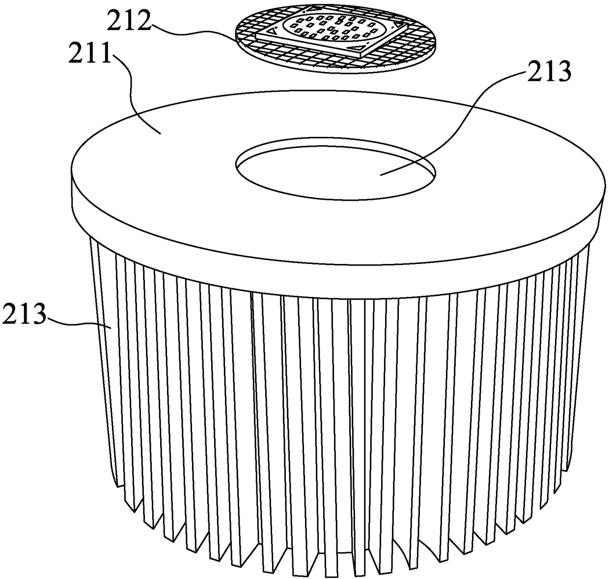
[0050] figure 1 and figure 2 As shown, the present invention relates to an LED lighting device with improved luminous flux density, including a power supply 1 , a heat sink 2 , a light source assembly 3 and a lens assembly 4 located in front of the light source assembly 3 .

[0051] Main features of the present invention are:

[0052] First: the light source assembly 3 has a light source substrate 31 and several LED crystal grains 32 welded and connected to the light source substrate 31. The light source substrate 31 adopts a positive and negative separation substrate; the use of a positive and negative separation...


PUM


Abstract

The invention discloses an LED light emitting device for improving luminous flux density, which comprises a power supply, a heat sink, a light source assembly and a lens assembly positioned in front of the light source assembly. The light source assembly comprises a light source substrate and a plurality of LED grains bonded and connected on the light source substrate, wherein the light source substrate adopts a positive-negative separation type substrate. The heat sink is a heat dissipation substrate integrally formed by cold forging and a heat dissipation fin connected on the heat dissipation substrate; a nickel plating layer is also formed on the bonding surfaces of the heat dissipation substrate and the light source substrate. The bonding surface of the heat dissipation substrate or the light source substrate is further formed with a groove communicating an inner region and an outer region of the bonding surface, a depth of the groove is greater than or equal to the thickness of the nickel plating layer, and the depth of the groove is smaller than the sum of the thickness of the nickel plating layer and the heat dissipation substratelight source substrate. Compared with the prior art, the invention can greatly improve the intensity of the luminous flux in the unit area and meet the requirements of factory lighting.

Description

technical field [0001] The invention relates to the field of LED lighting devices, in particular to an LED lighting device with improved luminous flux density, which can further solve the problems of light uniformity and overlapping shadows. Background technique [0002] Every time the power of the LED lighting device, especially the increase in the luminous flux per unit area (that is, the optical density), must be simultaneously optimized for the difficulty of heat dissipation, if the heat dissipation performance of the LED grains in the LED lighting device cannot be compared with If the power is increased synchronously, then the entire LED lighting device will not be practically put into use. [0003] Due to the above limitations, the LED lighting devices in the prior art either use dispersedly arranged LED grains or have low power, so that the luminous flux density of the light cannot be effectively improved, and furthermore, there are poor uniformity and easy The defec...

Claims


Application Information

Patent Timeline
IPC IPC(8): H01L33/64H01L33/58H01L33/48H01L25/075
CPCH01L33/642H01L25/0753H01L33/48H01L33/58
Inventor 张智丰黄泓豪陈必为
Owner 厦门吉来特光电有限公司
Why Eureka
Try Eureka