Multi-channel fluorescent optical fiber temperature transmitter and temperature measuring method

A technology of temperature transmitter and fluorescent optical fiber, applied in thermometers, thermometers with physical/chemical changes, instruments, etc., can solve the problems of large measurement errors and low precision, and achieve fast temperature acquisition speed, data stability and accuracy high degree of stability

Active Publication Date: 2021-04-09
西安和其光电科技股份有限公司
View PDF9 Cites 0 Cited by
  • Summary
  • Abstract
  • Description
  • Claims
  • Application Information

AI Technical Summary

Problems solved by technology

[0004] In order to solve the technical problems of large measurement errors and low precision in the existing temperature measurement method for the electrostatic chuck of the plasma etching machine, the present invention provides a multi-channel fluorescent optical fiber temperature transmitter and a temperature measurement method

Method used


Image

  • Multi-channel fluorescent optical fiber temperature transmitter and temperature measuring method
  • Multi-channel fluorescent optical fiber temperature transmitter and temperature measuring method
  • Multi-channel fluorescent optical fiber temperature transmitter and temperature measuring method

Examples


Embodiment 1

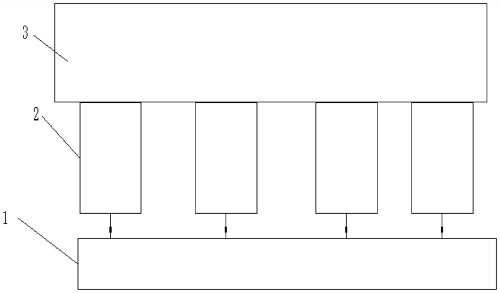
[0057] Such as figure 1 As shown, this embodiment uses the above-mentioned fluorescent optical fiber temperature sensor technology to propose a multi-channel fluorescent optical fiber temperature transmitter adapted to the plasma environment, including a data processing unit 1 and 4 temperature measurement units 2, 4 temperature measurement units 2 Temperature monitoring can be performed on different positions of the tested object; in other embodiments, the number of temperature measuring units 2 can be reasonably designed according to actual needs.

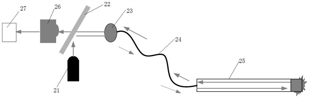
[0058] Such as figure 2 As shown, each temperature measurement unit 2 includes a light source generator 21, a filter plate 22, a filter lens 23, an optical fiber 24, an optical fiber probe 25, an optical sensor 26 and an amplifier 27, and the optical fiber probe 25 is arranged on the surface of the tested object 3; the light source generates The light beam emitted by the device 21 is incident on the filter 22, filtered and refl...

Embodiment 2

[0078] The difference from Example 1 is that step 2) obtains corresponding 4 first-time temperature data:

[0079] 2.1) Turn off the four light source generators 21;

[0080] 2.2) DMA controls 4 channels and simultaneously samples 4 channels at a sampling interval of 10us. DMA is the controller in data processing unit 1, and the 4 channels are respectively 4 temperature measurement units 2;

[0081] Four light sensors 26 simultaneously sample the first set of temperature data, and each channel collects the first sampling value A 1 ; With an interval of 10us, four light sensors 26 simultaneously sample the second set of temperature data, and each channel collects the second sampling value A 2 , 4 light sensors 26 obtain the first sampling value A of the excitation light for the first time 1 and the second sampled value A 2 ;

[0082] 2.3) With an interval of 10us, four light sensors 26 simultaneously sample the third set of temperature data, and each channel collects the th...

Embodiment 3

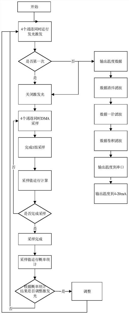
[0090] The difference from Embodiment 2 is that after multiple times of luminous excitation, the data processing unit 1 performs probability statistics on the temperature data obtained continuously by each temperature measuring unit 2, and according to the probability statistics results of the multiple continuous temperature data, Adjust the luminous intensity of the light source generator 21, specifically: when the proportion exceeding the predetermined setting value (threshold for short) in a plurality of continuous temperature data is greater than the required proportion, reduce the light intensity of the light source generator; When the proportion lower than the predetermined setting value (threshold value for short) is greater than the required proportion, the light intensity of the light source generator is increased. By adopting probability statistics data for the control of analog signal (sampling signal), the sampling signal control is adjusted by intelligent light sou...


PUM


Abstract

The invention provides a multi-channel fluorescent optical fiber temperature transmitter and a temperature measurement method, and solves the problems of large measurement error and low precision of an existing temperature measurement mode for an electrostatic chuck of a plasma etching machine. The method comprises the following steps: 1) M light source generators carry out first luminescence excitation; (2) the M light source generators are turned off, the M temperature measuring unit optical sensors carry out signal sampling of the ith exciting light, i is equal to 1, and the data processing unit processes sampling values obtained by the optical sensors to obtain M ith temperature data; 3) the M light source generators perform (i+1)th luminescence excitation; 4) the M light source generators are turned off, (i+1)th excitation light signal sampling is performed by the optical sensors of the M temperature measuring units, and sampling values obtained by the optical sensors by the data processing unit are processed to obtain M (i+1)th temperature data; meanwhile, the data processing unit filters and outputs the M ith temperature data; and 5) i=i+1, and it is returned to the step 3) until the temperature measurement is finished.

Description

technical field [0001] The invention relates to the field of optical fiber temperature measurement, in particular to a multi-channel fluorescent optical fiber temperature transmitter and a temperature measurement method. Background technique [0002] Plasma etching machine is an important equipment in the semiconductor production process, and it is particularly important to accurately measure the temperature of the electrostatic chuck during the etching process. [0003] At present, during the etching process of the existing plasma etching machine, the temperature measurement of the electrostatic chuck mainly adopts the metal platinum resistance temperature measurement method. The principle of metal platinum resistance temperature measurement: based on the principle that the resistance value of platinum resistance (PT100) is 100 ohms at 0 degrees Celsius, and its resistance value increases at a regular and uniform speed with the increase of temperature. The use of metal pla...

Claims


Application Information

Patent Timeline
Patent Type & Authority Applications(China)
IPC IPC(8): G01K11/32
CPCG01K11/3213Y02B20/40
Inventor 张文松邵飞胡波
Owner 西安和其光电科技股份有限公司
Why Eureka
Try Eureka