laboratory fume hood

A laboratory and fume hood technology, applied in the field of laboratory equipment, can solve problems such as uneven wind speed, affecting experimental results, and excessive wind speed in the work area, achieving the effects of convenient operation, ensuring safety, and simple mechanism

Active Publication Date: 2017-09-15
ANHUI YUAN LAB EQUIP
View PDF1 Cites 2 Cited by
  • Summary
  • Abstract
  • Description
  • Claims
  • Application Information

AI Technical Summary

Problems solved by technology

Existing fume hoods are provided with an air outlet on the top of the cabinet, and a fan is installed on the top. Since the air outlet is far away from the work area, if the harmful gas is to be completely removed, the wind speed of the fan is relatively large, which will make the work area The wind speed exceeds the standard. In addition, due to the rapid up and down movement of gas molecules, turbulent flow will be formed, resulting in uneven wind speed in the work area, incomplete absorption of harmful gases, and the wind speed is likely to affect the experimental results.
[0003] The Chinese Patent Publication No. is CN103624051A. The space on the worktable is used as the work area. A tapered duct with a narrow top and a wide bottom is installed on the top of the worktable. Uniformity and high wind speed, but it is still difficult to avoid harmful gas being inhaled by the human body during the operation process. Even if the air flow rate in the work area is relatively uniform, there is still the possibility of affecting the experimental results. Because the distance between the suction port and the operating table is relatively close, the staff The operation is inconvenient, and the fan should be kept on after the staff leave. Although harmful gases are avoided from entering the air, energy is wasted

Method used


Image

  • laboratory fume hood
  • laboratory fume hood

Examples


Embodiment Construction

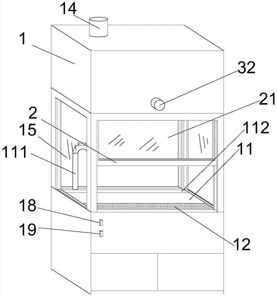
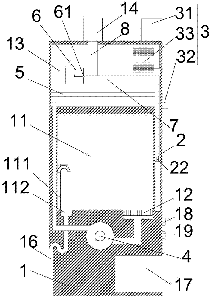
[0018] refer to figure 1 and figure 2 As shown, a kind of laboratory fume hood proposed by the present invention comprises a cabinet body 1, a cabinet door 2 and a control mechanism 3;

[0019] A fan 4, a filter screen 5, a shunt pipe 6, a first air guide pipe 7 and a second air guide pipe 8 are installed in the cabinet body 1; an operating room 11, an air inlet channel 12 and a filter chamber 13 are arranged in the cabinet body 1, The cabinet door 2 is movably installed on the cabinet body 1 and is located on one side of the operating room 11. The movement of the cabinet door 2 can adjust the contact area between the operating room 11 and the external connection. The first observation window 21 is installed on the cabinet door 2; the air inlet channel 12 is located at the bottom of the operating room 11 close to the side of the cabinet door 2, the air inlet channel 12 is connected to the air inlet of the fan 4, and the air outlet of the fan 4 is connected to the filter cham...


PUM


Abstract

The invention provides a fume cupboard for a laboratory. The fume cupboard comprises a cupboard body, a cupboard door and a control mechanism. A fan, a filter net, a flow distribution pipe, a first air guide pipe and a second air guide pipe are installed in the cupboard body. An operation room, an air inlet channel and a filter cavity are formed in the cupboard body. The cupboard door is provided with a first observation window. The bottom of the cupboard door is provided with a first air outlet channel, and the top of the cupboard body is provided with a second air outlet channel. An air outlet of the flow distribution pipe is communicated with the first air outlet channel through the first air guide pipe and communicated with the second air outlet channel through the second air guide pipe. A flow distribution valve is installed in the flow distribution pipe in a rotatable mode. The control mechanism comprises a control device, an infrared sensing device and a driving device. The driving device is in driving connection with the cupboard door. The control device is in communication connection with the infrared sensing device, the driving device and the fan. According to the fume cupboard for the laboratory, harmful gas can be effectively prevented from being inhaled by the human body, experimental operation is convenient, operation objects are almost not affected by the wind speed in the experiment process, and meanwhile energy can be saved.

Description

technical field [0001] The invention relates to laboratory equipment, in particular to a laboratory fume hood. Background technique [0002] The fume hood is a kind of local exhaust equipment commonly used in the laboratory. The fume hood can completely and timely discharge the harmful gas from the workplace, and can prevent the operator from inhaling toxic, harmful and odorous gas, which has played a very good role in the operation of the operator. Protective effects. The fume hood is usually equipped with a zone, the operator conducts experiments in the work area, and the fan on the top of the fume hood discharges harmful gases. Existing fume hoods are provided with an air outlet on the top of the cabinet, and a fan is installed on the top. Since the air outlet is far away from the work area, if the harmful gas is to be completely removed, the wind speed of the fan is relatively large, which will make the work area The wind speed exceeds the standard. In addition, due to...

Claims


Application Information

Patent Timeline
Patent Type & Authority Patents(China)
IPC IPC(8): B08B15/02
CPCB08B15/023B08B2215/00
Inventor 张然袁巍王跃
Owner ANHUI YUAN LAB EQUIP
Why Eureka
Try Eureka