
Plate feeding machine

A technology of sheet metal and feeding machine, applied in stone processing tools, stone processing equipment, work accessories, etc., can solve the problems of slow loading and low efficiency, and achieve the effect of high loading efficiency, stable performance, flexible and reliable use

Inactive Publication Date: 2015-10-21
刘艾爱 +1
View PDF6 Cites 5 Cited by
  • Summary
  • Abstract
  • Description
  • Claims
  • Application Information

AI Technical Summary

Problems solved by technology

[0003] The purpose of the present invention is to provide a plate feeding device to solve the problems of slow feeding and low efficiency of the current plate cutting machine

Method used


Image

  • Plate feeding machine

Examples


Embodiment Construction

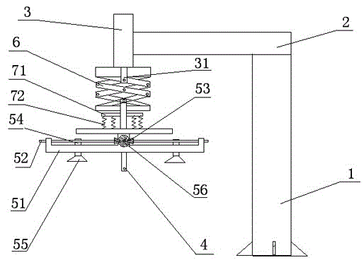
[0013] Such as figure 1 As shown, a plate loading machine includes a column 1, a cross arm 2, a vertical oil cylinder 3, a suction cup mechanism, a stroke mechanism, and a position sensor 4,

[0014] The top of the column 1 is connected to one end of the cross arm 2 through a rotating mechanism, the cross arm 2 rotates 360 degrees around the column, and the other end of the cross arm 2 is fixedly connected to the vertical cylinder 3,

[0015] The suction cup mechanism comprises a suction cup frame 51, a suction cup motor, and two ball screw screws 52. Two ball screw screws 52 are installed inside the suction cup frame, and an umbrella wheel 53 is installed at one end of the ball screw screw 52, ​​and two umbrella wheels 53 are connected with the suction cup motor shaft. The umbrella wheel 56 of the motor cooperates, and the sucker 55 is installed on the bottom of the screw nut 54,

[0016] The stroke mechanism is a scissor-type lifting frame 6, the upper end is connected with...


PUM


Abstract

The invention aims to provide a plate feeding machine. The plate feeding machine comprises a stand column, a cross arm, a vertical oil cylinder, a sucker mechanism, a travel mechanism and a position sensor. The top end of the stand column and one end of the cross arm are connected through a rotating mechanism. The other end of the cross arm is fixedly connected with the vertical oil cylinder. The sucker mechanism comprises a sucker frame, a sucker motor and two ball screws. The travel mechanism is a scissors-type structure lifting frame. The upper end of the travel mechanism is connected with a piston rod of the vertical oil cylinder. The lower end of the travel mechanism is connected with the sucker frame. The position sensor is installed on the sucker frame. The problem that an existing plate cutting machine is low in discharging speed and low in efficiency is solved.

Description

technical field [0001] The invention belongs to the field of feeding devices, in particular to a feeding device for a plate cutting machine. Background technique [0002] Marble slabs are widely used building decoration materials. With the continuous development of science and technology and the continuous improvement of slab cutting equipment, the efficiency of slab cutting has been greatly improved, but the slab loading and unloading devices have not been sufficiently improved. It has become a major bottleneck restricting the plate cutting industry. How to change the existing loading and unloading devices has become the focus of attention of technicians in the plate cutting field. Contents of the invention [0003] The object of the present invention is to provide a board material feeding device to solve the problems of slow feeding and low efficiency of the current board material cutting machine. [0004] In order to solve the above problems, the technical solution of ...

Claims


Application Information

Patent Timeline
IPC IPC(8): B28D1/22B28D7/00
CPCB28D1/22B28D7/00B28D7/005
Inventor 刘艾爱李倩
Owner 刘艾爱
Learn More