
On-chip tri-state signal detection device and detection method thereof

A detection device and tri-state signal technology, applied in the direction of measurement device, measurement of electricity, measurement of electric variables, etc., can solve the problems of large static power consumption current, consumption of chip area, large input voltage range limitation, etc., to achieve high reliability , The effect of wide supply voltage range and low power consumption

Active Publication Date: 2018-05-25
SICHUAN YICHONG TECH CO LTD
View PDF7 Cites 0 Cited by
  • Summary
  • Abstract
  • Description
  • Claims
  • Application Information

AI Technical Summary

Problems solved by technology

[0004] This detection of the tri-state signal by detecting the internal voltage of the high-resistance resistor string will directly lead to two more prominent problems: 1. The on-chip high-resistance resistor string will consume considerable chip area or generate large static power. Current consumption; 2. This detection method has a large limit on the range of input voltage, and it is difficult to cover digital integrated circuits under different production processes.

Method used


Image

  • On-chip tri-state signal detection device and detection method thereof
  • On-chip tri-state signal detection device and detection method thereof
  • On-chip tri-state signal detection device and detection method thereof

Examples


Embodiment Construction

[0014] In order to make the object, technical solution and advantages of the present invention more obvious, the present invention will be further described in detail below in conjunction with specific embodiments and with reference to the accompanying drawings.

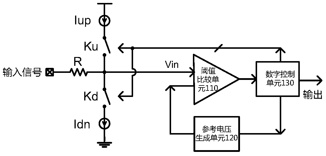
[0015] figure 1 It is a structural diagram of a three-state signal detection device according to an embodiment of the present invention. The tri-state signal detection device includes a resistor R, a current source Iup, a switch Ku, a current source Idn, a switch Kd, a threshold comparison unit 110 , a reference voltage generation unit 120 , and a digital control unit 130 .

[0016] figure 1 Among them, one end of the resistor R is connected to the tri-state input signal, the other end is connected to the chip pin Vin end, and the Vin end is used as an input end of the threshold comparison unit 110; the other input end of the threshold comparison unit 110 is connected to the reference The output terminal of the vol...


PUM


Abstract

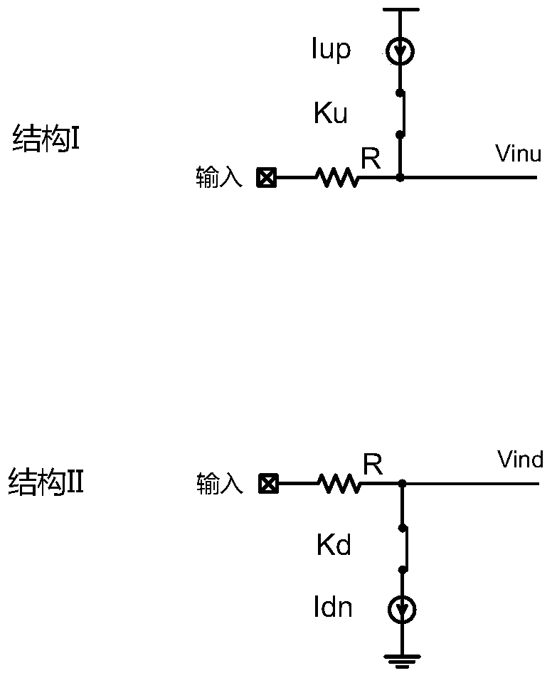
The invention relates to an on-chip tristate signal detection device and a detection method thereof. The detection device includes a first current source, a second current source, a first switch, a second switch, a threshold comparison unit, and a digital control unit. The first current source is connected to the first end of the first switch, the second end of the first switch is connected to the first end of the second switch, and the second end of the second switch is connected to the second current source. The digital control unit controls the closing and / or opening of the first switch, the second switch to form two different topological structures. Based on one of the topologies, the threshold comparison unit first input receives a voltage associated with a tri-state input signal. The second input terminal of the threshold comparison unit receives a reference voltage, and compares the magnitude relationship between the relevant voltage and the reference voltage, so that the digital control unit can detect the state of the input signal based on the comparison result. The invention has low detection power consumption and high reliability of detection results, and can be widely used in the field of on-chip detection of chip interface signals.

Description

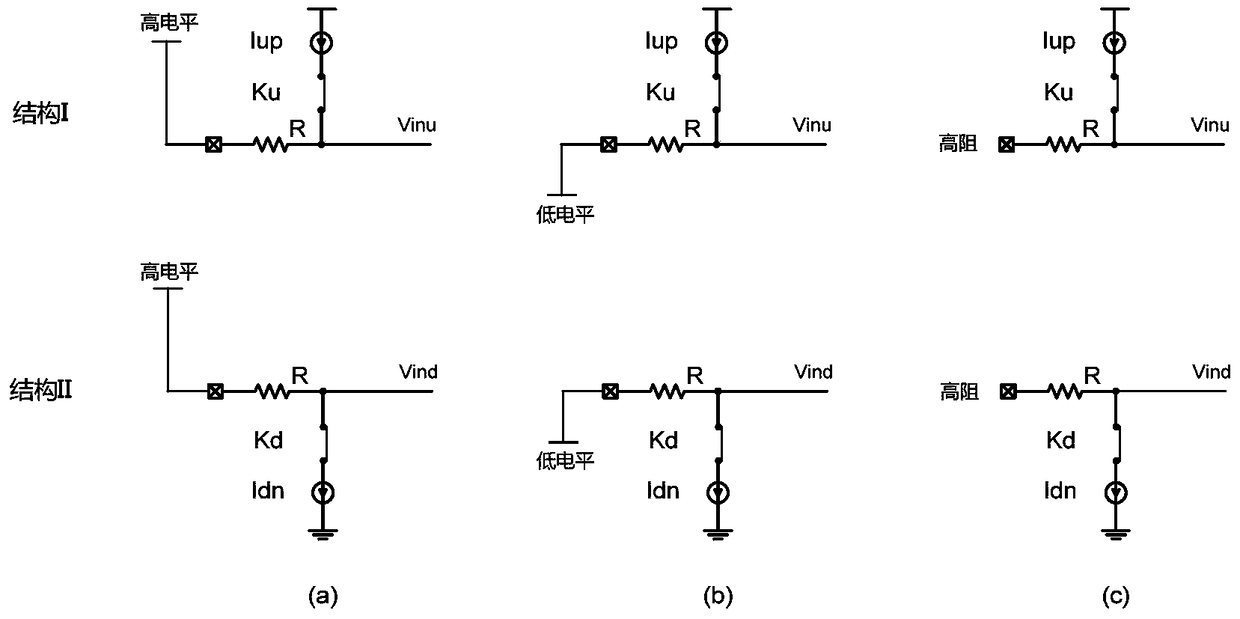
technical field [0001] The invention relates to the field of digital integrated circuits, in particular to the field of chip interface signal detection. Background technique [0002] The tri-state signal (Tri-State or T / S) includes three signal states of high level, low level, and high-impedance state (also known as forbidden state). Devices with these three signal states are called tri-state gates. [0003] In chip input control, tri-state signals are usually used to control chip pins to achieve more configurable states, so that pin resources with a limited number of chips can be used more effectively. At present, the three-state signal detection method is usually to connect the signal to be tested to the internal node of the high-resistance resistor string between the power supply and the ground, by comparing the voltage values ​​of other nodes in the high-resistance resistor string, and according to different detection The results are combined to enable identification o...

Claims


Application Information

Patent Timeline
Patent Type & Authority Patents(China)
IPC IPC(8): G01R31/3181
Inventor 陈晓龙沈煜金学成
Owner SICHUAN YICHONG TECH CO LTD
Learn More