Debris flow disaster monitoring equipment

A technology for monitoring equipment and debris flow, applied in the direction of instruments, alarms, etc., can solve the problems of low equipment cost, inaccurate early warning, high cost, etc., and achieve the effect of low equipment cost

Active Publication Date: 2015-10-21
CHENGDU HANKANG INFORMATION IND
View PDF6 Cites 8 Cited by
  • Summary
  • Abstract
  • Description
  • Claims
  • Application Information

AI Technical Summary

Problems solved by technology

[0008] The invention provides a mud-rock flow disaster monitoring device, which solves the technical problem that the existing mud-rock flow early warning equipment has a high cost, and cannot give early warning of the flow direction and specific flow position of the mud-rock flow, and the early warning is inaccurate. It is relatively low, and can give early warning of the flow direction and specific flow location of debris flow, and the technical effect of early warning is more accurate

Method used


Image

  • Debris flow disaster monitoring equipment

Examples


Embodiment 1

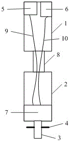
[0023] In the first embodiment, debris flow disaster monitoring equipment is provided, please refer to figure 1 , the equipment includes:

[0024] N monitoring structures, the N monitoring structures are evenly distributed in the monitored area, and the N is a positive integer greater than or equal to 100, wherein the monitoring structure includes: a first cylinder 1, a second cylinder 2, a fixed main nail 3. Wherein, the upper end of the spring column 8 is connected to the lower end of the first cylinder, the lower end of the spring column is connected to the upper end of the second cylinder, the upper end of the fixed main nail is connected to the lower end of the second cylinder, and the fixed main nail is connected to the lower end of the second column. The lower end of the nail is pre-embedded under the ground in the detection area, and four fixed support nails 4 are connected to the surface of the fixed main nail. A GPS positioning module 5 and a wireless communication m...


PUM


Abstract

The invention discloses debris flow disaster monitoring equipment, which comprises N monitoring structures. Each monitoring structure comprises a first cylinder, a second cylinder and a fixed main nail, the lower end of the fixed main nail is embedded under the ground of a detected region in advance, a GPS positioning module and a wireless communication module are arranged in the first cylinder, a storage battery is arranged in the second cylinder, the GPS positioning module is connected with the storage battery through a first lead wire, the wireless communication module is connected with the storage battery through a second lead wire, the first lead wire and the second lead wire pass through a spring cylinder, and the first lead wire and the second lead wire are in a strained state. The debris flow disaster monitoring equipment achieves the technical effects of being capable of warning flow direction of the debris flow and specific position where the debris flow is flowing to in advance, and being accurate in early warning at low equipment cost.

Description

technical field [0001] The invention relates to the research field of early warning of geological disasters, in particular to monitoring equipment for debris flow disasters. Background technique [0002] Debris flow refers to a special torrent carrying a large amount of sediment and stones due to landslides caused by heavy rain, snowstorm or other natural disasters in mountainous areas or other areas with deep valleys and steep terrain. Debris flow is sudden and fast, and the flow rate Large, large material capacity and strong destructive power, debris flow often destroys roads, railways and other transportation facilities and even villages and towns, causing huge losses. [0003] Debris flow is a torrent formed by heavy rain and floods after saturation and dilution of soft soil mountains containing sand and rocks. Its area, volume and flow are large, while landslides are areas of small areas of diluted soil mountains. Typical debris flows are caused by suspended It is com...

Claims


Application Information

Patent Timeline
Patent Type & Authority Applications(China)
IPC IPC(8): G08B21/10
CPCG08B21/10
Inventor 柴军陈静陈郁良耿红珍
Owner CHENGDU HANKANG INFORMATION IND
Why Eureka
Try Eureka