Display panel and driving method and driving device thereof

A technology for display panels and driving methods, applied to static indicators, instruments, etc., can solve the problems of reducing the display resolution of the display panel and increasing the display power consumption of the display panel, and achieve the effect of reducing display power consumption and reducing display resolution

Inactive Publication Date: 2015-10-21
BOE TECH GRP CO LTD +1
View PDF6 Cites 14 Cited by
  • Summary
  • Abstract
  • Description
  • Claims
  • Application Information

AI Technical Summary

Problems solved by technology

[0004] In summary, the existing display panels cannot selectively reduce the display re...

Method used


Image

  • Display panel and driving method and driving device thereof
  • Display panel and driving method and driving device thereof
  • Display panel and driving method and driving device thereof

Examples


Embodiment 1

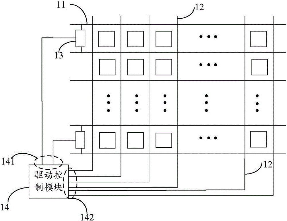
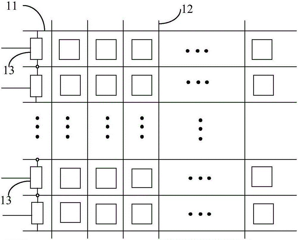
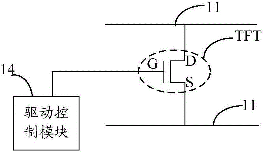
[0136] see figure 1 1. A display panel provided by an embodiment of the present invention, the display panel includes gate lines 11 and data lines 12 arranged crosswise, and the display panel further includes at least one switch unit 13 connected between different gate lines 11 ( figure 1 Only a few are drawn in, but not limited to the connection in this figure), the switch unit 13 is used to control whether at least two rows of gate lines 11 are turned on; ( figure 1 The squares included in the area where the data line and the gate line intersect represent sub-pixel units)

[0137] And, a drive control module 14 connected to the control terminal of the switch unit and the input terminal of the data line respectively, the drive control module 14 includes a first output terminal 141 connected to the control terminal of the switch unit one by one, and through the first output The terminal 141 outputs a control signal for controlling whether the corresponding switch unit 13 is t...

Embodiment 2

[0224] It should be noted that the driving method provided in this embodiment is also based on the display panel provided in Embodiment 1, and the maximum resolution of the display panel mentioned in Embodiment 2 is the same as that in Embodiment 1.

[0225] see Figure 8 , another method for driving a display panel provided by an embodiment of the present invention, the method includes:

[0226] S801. Receive the voltage signal of the image to be displayed sent by the signal source;

[0227] S802. Determine the current image display mode according to the voltage signals of two adjacent frames of images to be displayed, wherein the image display mode is a static display mode or a dynamic display mode;

[0228] It should be noted that the two adjacent frames refer to the frame and the previous frame when the voltage signal of the image to be displayed is ready to be transmitted.

[0229] Among them, the current image display mode is determined according to the voltage signals...


PUM


Abstract

The invention provides a display panel and a driving method and a driving device thereof in order to selectively reduce the display resolution of the display panel and reduce the display power consumption of the display panel. The display panel comprises grid lines and data lines which are arranged in a cross manner. The display panel further comprises at least one switching unit connected between different grid lines and respectively used for controlling whether at least two grid lines are switched on or not, and a drive control module connected with the control ends of the switching units and the input ends of the data lines. The drive control module includes a first output end connected with the control ends of the switching units one by one, and outputs control signals used for controlling whether the corresponding switching units are switched on or not through the first output end. The drive control module further includes a second output end connected with the input ends of the data lines one by one, and decides whether or not to output image signals to the corresponding data lines through the second output end according to the on-off state of the switching units.

Description

technical field [0001] The invention relates to the field of liquid crystal display systems, in particular to a display panel, a driving method and a driving device thereof. Background technique [0002] With the continuous development of display technology, the requirements for the display resolution of the display panel are getting higher and higher. The display resolution of the existing display panel can be divided into ultra high definition display panel (Ultra High Definition, UHD), full high definition display panel (Full High Definition, FHD) and high-definition display panel (High Definition, FHD). However, most of the current module products use an unchanging pixel structure, that is, the resolution is not variable. For example, when the display panel is an ultra-high-definition display panel, and the resolution of the image to be displayed is relatively low and belongs to the resolution range of high-definition display, when the image is displayed on the ultra-hi...

Claims


Application Information

Patent Timeline
IPC IPC(8): G09G3/36
CPCG09G3/20G09G2300/0408G09G2300/08G09G2310/0205G09G2310/0267G09G2320/103G09G2340/0435G09G2320/0613G09G2330/021G09G2340/0407
Inventor 高博王秀荣张浩时凌云董学李亚飞
Owner BOE TECH GRP CO LTD
Why Eureka
Try Eureka