Autofocus image projection apparatus

a projection apparatus and image technology, applied in the direction of printers, cameras, instruments, etc., can solve the problems of reducing the aperture ratio, and increasing the size of the projector, so as to reduce the display resolution and suppress the increase in the size of the apparatus

Inactive Publication Date: 2011-07-28
CANON KK
View PDF1 Cites 3 Cited by
  • Summary
  • Abstract
  • Description
  • Claims
  • Application Information

AI Technical Summary

Benefits of technology

[0009]The present invention provides an image projection apparatus capable of performing good AF while suppressing increase in size of the apparatus and reduction of display resolution.

Problems solved by technology

However, the projector disclosed in Japanese Patent No. 2919585 requires a dedicated optical member for forming an optical path to introduce light from the half-mirror to the image-pickup element, which increases in size of the projector.
This requires a space to retract the half-mirror, which makes the projector larger in size.
The reduction of the aperture ratio invites deterioration of basic performances of the projector such as reduction of brightness of projected images.
Increasing the aperture ratio needs reduction of resolution or increase in size of the liquid crystal panel, which prevents achievement of a small and high-resolution projector.

Method used


Image

  • Autofocus image projection apparatus
  • Autofocus image projection apparatus
  • Autofocus image projection apparatus

Examples


embodiment 1

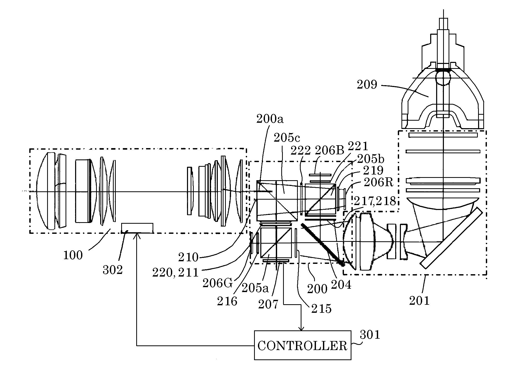
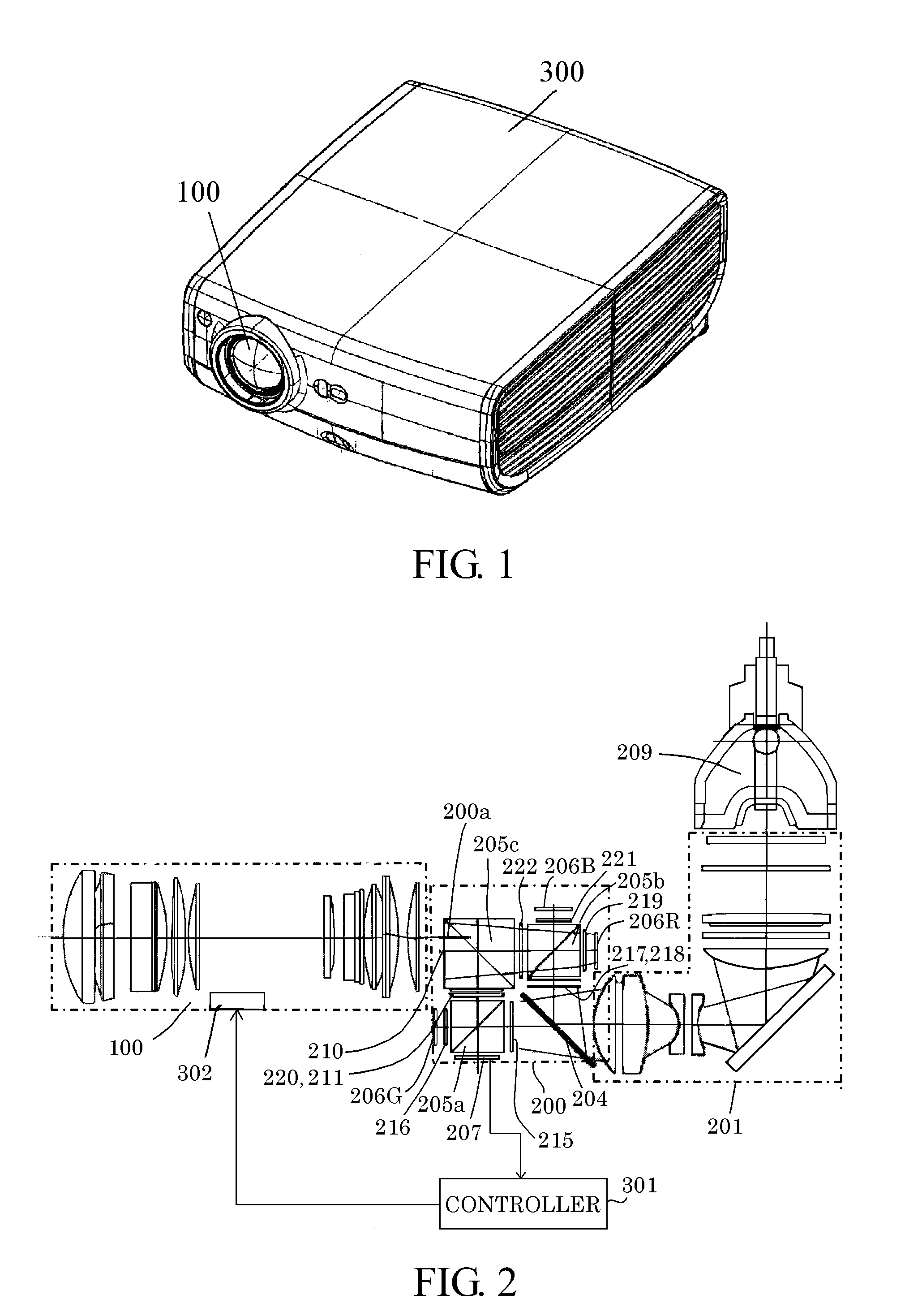
[0020]FIG. 1 shows a liquid crystal projector as an image projection apparatus that is a first embodiment (Embodiment 1) of the present invention. Reference numeral 300 denotes a chassis of the projector, and reference numeral 100 denotes a projection lens serving as a projection optical system.

[0021]FIG. 2 shows an optical configuration of the projector of Embodiment 1. Reference numeral 209 denotes a light source lamp, and reference numeral 201 denotes an illumination optical system. The illumination optical system 201 includes optical elements such as lenses for dividing illumination light from the light source lamp 209 into plural light fluxes and then overlapping them on liquid crystal panels which will be described later, and a polarization conversion element for converting the illumination light into polarized light having a predetermined polarization direction. The illumination optical system 201 further includes a mirror for bending an optical path in the illumination optic...

embodiment 2

[0055]FIG. 7 shows a configuration of a color separation / combination unit 200′ in a second embodiment (Embodiment 2) of the present invention. In FIG. 7, components common to those shown in FIG. 6 are denoted by same reference numerals as those in FIG. 6, and descriptions thereof are omitted

[0056]FIG. 7 also shows an optical path of an R light that is separated from illumination light from an illumination optical system 201 by the color separation / combination unit 200′, image-modulated by an R-liquid crystal panel 206R and combined with other color lights by the color separation / combination unit 200′ to be projected onto a projection surface through a projection lens 100, and an optical path of the R light that is reflected by the projection surface to reach an image-pickup element 207. In the figure, solid line arrows show optical paths of a P-polarized light, dotted line arrows show optical paths of an S-polarized light, and white arrows show optical paths of a circularly-polarize...


PUM


Abstract

The image projection apparatus includes a color separation/combination unit separating light into color lights to introduce them to light modulation elements and combining the lights modulated by the light modulation elements, a projection optical system projecting projection light that is the combined color lights onto a projection surface, an image-pickup element capturing a projected image, and a controller performing AF by using an output from the image-pickup element. The color separation/combination unit includes an optical film surface reflecting or transmitting at least one of the color lights and a non-effective surface. The image-pickup element is disposed so as to face the non-effective surface and captures the projected image using detection light of the projection light, which is reflected at the projection surface to enter the color separation/combination unit through the projection optical system and is transmitted through or reflected at the film surface to exit through the non-effective surface.

Description

BACKGROUND OF THE INVENTION[0001]1. Field of the Invention[0002]The present invention relates to an image projection apparatus such as a projector, and particularly to an image projection apparatus having an autofocus (AF) function for its projection optical system.[0003]2. Description of the Related Art[0004]Projectors modulate light from a light source by a light modulation element such as a liquid crystal panel and project the modulated light through a projection optical system (projection lens) onto a projection surface such as a screen to display an image. Such projectors include one having an AF function to automatically adjust a focus state of the projection optical system in order to display an in-focus image regardless of a distance to the projection surface (projection distance).[0005]Japanese Patent No. 2919585 discloses a projector that includes a half-mirror disposed in an optical path between a projection lens and a liquid crystal panel, and captures a projected image ...

Claims


Application Information

Patent Timeline
Patent Type & Authority Applications(United States)
IPC IPC(8): G03B3/12G03B21/14
CPCG03B21/53G03B13/36
Inventor SAWAHATA, TAKASHI
Owner CANON KK
Why Eureka
Try Eureka