Theta z drive apparatus and stage apparatus

a technology of drive apparatus and stage apparatus, which is applied in the direction of photomechanical apparatus, propulsion systems, instruments, etc., can solve the problems of warpage or distortion easily generated in such a substrate, inclination may interfere with process, and substrate thinning and increasing diameter, so as to suppress the increase in the size of the apparatus

Inactive Publication Date: 2013-02-07
YASKAWA DENKI KK
View PDF10 Cites 5 Cited by
  • Summary
  • Abstract
  • Description
  • Claims
  • Application Information

AI Technical Summary

Benefits of technology

[0009]The present invention has been proposed in order to solve the aforementioned problems, and an object of the present invention is to provide a θZ drive apparatus and a stage apparatus each capable of adjusting an inclination of a stage with respect to a horizontal plane while suppressing increase in the size of the apparatus.
[0011]In this θZ drive apparatus according to the first aspect, as hereinabove described, the Z-direction drive coil of the single actuator is divided into the at least three coil portions capable of being supplied with current independently of each other, and the at least three coil portions are arranged to be capable of driving the stage in the direction Z, the direction θx which is the rotation direction employing the direction X in the horizontal plane as a center line of rotation, and the direction θy which is the rotation direction employing the direction Y in the horizontal plane orthogonal to the direction X as a center line of rotation, whereby the stage can be driven in the direction Z, the direction θx which is the rotation direction employing the direction X in the horizontal plane as a center line of rotation, and the direction θy which is the rotation direction employing the direction Y in the horizontal plane orthogonal to the direction X as a center line of rotation in response to current independently supplied to the at least three coil portions. Thus, even if a substrate placed on the stage through a substrate holding mechanism is slightly inclined with respect to the horizontal plane, the actuator can adjust the inclination of the stage (substrate) with respect to the horizontal plane. Furthermore, the single actuator can drive the stage in the direction θx and the direction θy in addition to the direction Z, and hence increase in the size of the apparatus can be suppressed even if a mechanism performing driving in the direction θx and the direction θy is added. Therefore, in this θZ drive apparatus according to the first aspect, the inclination of the stage with respect to the horizontal plane can be adjusted while increase in the size of the apparatus is suppressed.
[0013]In this stage apparatus according to the second aspect, as hereinabove described, the Z-direction drive coil of the single actuator of the θZ drive portion is divided into the at least three coil portions capable of being supplied with current independently of each other, and the at least three coil portions are arranged to be capable of driving the stage in the direction Z, the direction θx which is the rotation direction employing the direction X in the horizontal plane as a center line of rotation, and the direction θy which is the rotation direction employing the direction Y in the horizontal plane orthogonal to the direction X as a center line of rotation, whereby the stage of the θZ drive portion can be driven in the direction Z, the direction θx which is the rotation direction employing the direction X in the horizontal plane as a center line of rotation, and the direction θy which is the rotation direction employing the direction Y in the horizontal plane orthogonal to the direction X as a center line of rotation in response to current independently supplied to the at least three coil portions. Thus, even if a substrate placed on the stage through a substrate holding mechanism is slightly inclined with respect to the horizontal plane, the actuator of the θZ drive portion can adjust the inclination of the stage (substrate) with respect to the horizontal plane. Furthermore, the single actuator can drive the stage in the direction θx and the direction θy in addition to the direction Z, and hence increase in the size of the apparatus can be suppressed even if a mechanism performing driving in the direction θx and the direction θy is added. Therefore, in this stage apparatus according to the second aspect, the inclination of the stage of the θZ drive portion with respect to the horizontal plane can be adjusted while increase in the size of the apparatus is suppressed.

Problems solved by technology

Meanwhile, in recent years, the substrate such as a semiconductor wafer tends to be thinned and increased in diameter, and warpage or distortion is easily generated in such a substrate.
Therefore, even if the substrate is slightly inclined with respect to a horizontal plane, the inclination may interfere with process such as exposure, inspection, or the like.
However, although the θZ drive portion of the stage apparatus according to the aforementioned Japanese Patent Laying-Open No. 2007-027659 can drive the stage in the direction Z and the direction θz, the same cannot drive the stage in a direction θx and a direction θy about respective axes in a direction X and a direction Y orthogonal to each other in a horizontal plane.
Therefore, when a substrate placed on the stage is slightly inclined with respect to the horizontal plane, there is such a problem that the stage cannot be driven to adjust the inclination thereof.
Furthermore, in the aforementioned Japanese Patent Laying-Open No. 2007-027659, a mechanism performing driving in the direction θx and the direction θy may be added, but in this case, such a problem that the apparatus increases in size may newly arise.

Method used


Image

  • Theta z drive apparatus and stage apparatus
  • Theta z drive apparatus and stage apparatus
  • Theta z drive apparatus and stage apparatus

Examples


first embodiment

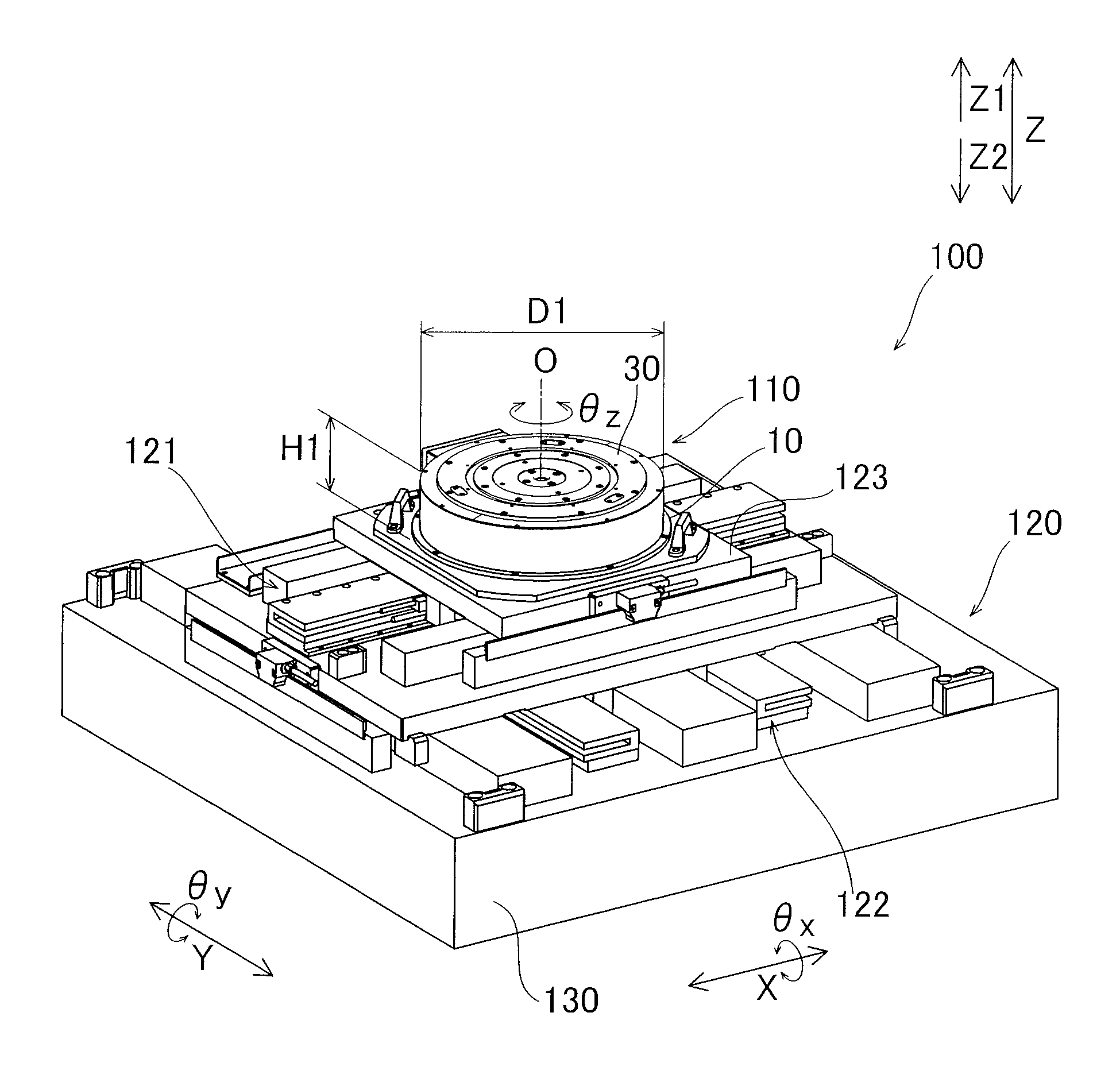
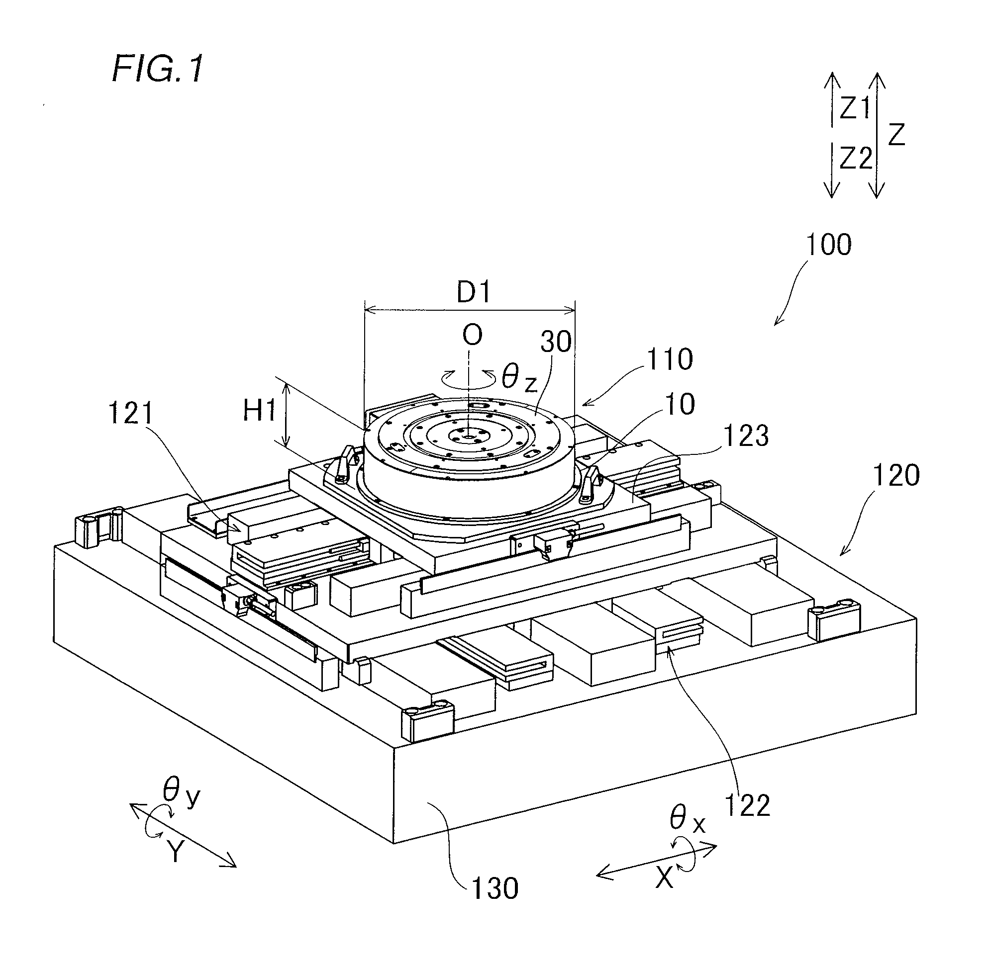
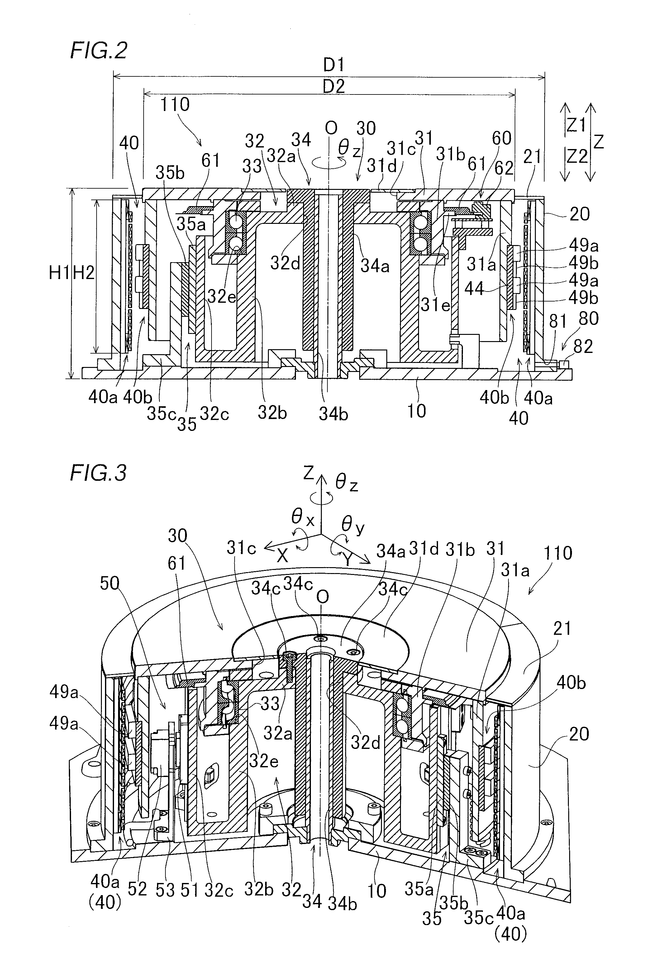
[0031]First, the structure of an XYθZ stage 100 including a θZ stage unit 110 according to a first embodiment is described with reference to FIGS. 1 to 12. In the first embodiment, an example of applying the present invention to the six-axis XYθZ stage 100 including the θZ stage unit 110 employed as a stage to position an exposure apparatus, an inspection apparatus, or the like for a semiconductor wafer is described. The θZ stage unit 110 is an example of the “θZ drive apparatus” or the “θZ drive portion”, and the XYθZ stage 100 is an example of the “stage apparatus”.

[0032]As shown in FIG. 1, the XYθZ stage 100 according to the first embodiment is mounted on a surface plate 130 hardly affected by disturbance. The XYθZ stage 100 includes the θZ stage unit 110 and an XY stage unit 120. The θZ stage unit 110 is a unit to perform positioning (positioning in a direction Z and a direction θz) of a semiconductor wafer or the like placed on a stage 30 by driving the stage 30 in the vertical...

second embodiment

[0090]Next, a second embodiment is described with reference to FIGS. 13 to 16. In this second embodiment, an actuator has two movable elements, dissimilarly to the aforementioned first embodiment in which the aforementioned actuator has the single movable element.

[0091]As shown in FIG. 13, a θZ stage unit 200 according to the second embodiment includes a base portion 210, a frame 220, a stage 230 having an upper surface on which a substrate holding mechanism (not shown) or the like to hold a substrate such as a semiconductor wafer is placed, and a single actuator 240 driving the stage 230. The frame 220 has a cylindrical shape and is fixedly set on the base portion 210. The frame 220 constitutes the outer surface portion of the θZ stage unit 200.

[0092]The stage 230 includes a rotary table 231 constituting the upper surface side of the θZ stage unit 200 and an elevating table 232 supporting the rotary table 231 to be rotatable in a direction θz. The rotary table 231 includes a cylind...


PUM


Abstract

In this θZ drive apparatus, at least three coil portions are arranged to be capable of driving a stage in a direction Z, a direction θx which is a rotation direction employing a direction X in a horizontal plane as a center line of rotation, and a direction θy which is a rotation direction employing a direction Y in the horizontal plane orthogonal to the direction X as a center line of rotation.

Description

CROSS-REFERENCE TO RELATED APPLICATIONS[0001]The priority application number JP2010-088272, θZ Drive Apparatus and Stage Apparatus, Apr. 7, 2010, Yoshiaki Kubota, Toru Shikayama, Yoichiro Dan, and Toshiyuki Kono, upon which this patent application is based is hereby incorporated by reference. This application is a continuation of PCT / JP2010 / 072075, θZ Drive Apparatus and Stage Apparatus, Dec. 9, 2010, Yoshiaki Kubota, Toru Shikayama, Yoichiro Dan, Toshiyuki Kono, and Akihito Toyoda.BACKGROUND OF THE INVENTION[0002]1. Field of the Invention[0003]The present invention relates to a θZ drive apparatus and a stage apparatus, and more particularly, it relates to a θZ drive apparatus and a stage apparatus each including a stage driven in the vertical direction (direction Z) and a rotation direction (direction θz).[0004]2. Description of the Background Art[0005]In general, a θZ drive apparatus and a stage apparatus each including a stage driven in the vertical direction (direction Z) and a ...

Claims


Application Information

Patent Timeline
Patent Type & Authority Applications(United States)
IPC IPC(8): H02K41/02
CPCG03F7/70758H01L21/0274H01L21/682
Inventor KUBOTA, YOSHIAKISHIKAYAMA, TORUDAN, YOICHIROKONO, TOSHIYUKITOYODA, AKIHITO
Owner YASKAWA DENKI KK
Why Eureka
Try Eureka