Wireless router and method for switching master antenna and standby antenna thereof

A wireless router and antenna switching technology, which is applied in wireless communication, radio transmission system, diversity/multi-antenna system, etc., can solve the problem of small wireless signal coverage, affecting users' wireless network access needs, wireless signal ups and downs, etc. problems, to achieve the effect of solving signal receiving problems and ensuring wireless network access requirements

Inactive Publication Date: 2015-10-21
SHENZHEN ATUE TECH CO LTD
View PDF6 Cites 8 Cited by
  • Summary
  • Abstract
  • Description
  • Claims
  • Application Information

AI Technical Summary

Problems solved by technology

Traditional wireless routers are generally only equipped with the main antenna system. When the main antenna system is in poor contact or damaged, the wireless router cannot effectively receive wireless signals. For example, the wireless signal may be intermittent or the wireless signal coverage may be small. problems, thus affecting the normal wireless network access needs of users

Method used


Image

  • Wireless router and method for switching master antenna and standby antenna thereof
  • Wireless router and method for switching master antenna and standby antenna thereof

Examples


Embodiment Construction

[0020] In order to make the technical problems, technical solutions and beneficial effects solved by the present invention clearer, the following further describes the present invention in detail with reference to the accompanying drawings and embodiments. It should be understood that the specific embodiments described herein are only used to explain the present invention, but not to limit the present invention.

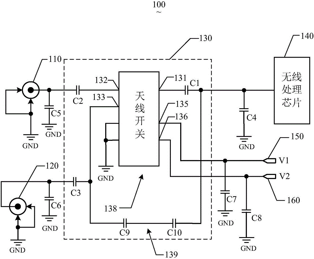
[0021] See figure 1 , Is a schematic structural diagram of an implementation manner of the wireless router provided by the present invention. The wireless router 100 includes a main antenna 110, a backup antenna 120, an antenna switch circuit 130, and a wireless processing chip 140. The main antenna 110 and the backup antenna 120 have the same gain, and they are connected to the antenna switch. 130, and is further connected to the wireless processing chip 140 through the antenna switch 130.

[0022] Specifically, the antenna switch circuit 130 includes an antenna switch ...


PUM


Abstract

The invention provides a wireless router comprising a master antenna, a standby antenna, an antenna switch circuit, and a wireless processing chip. The master antenna and the standby antenna are connected with the wireless processing chip through the antenna switch circuit. The antenna switch circuit comprises an antenna switch. The wireless processing chip is used for detecting the signal intensities of the master antenna and the standby antenna and controlling the antenna switch to be switched to a state in which the antenna switch circuit is used for transmitting and receiving wireless signals when the signal intensity of the master antenna is a preset value lower than that of the standby antenna. The invention also provides a method for switching the master antenna and the standby antenna of the wireless router.

Description

Technical field [0001] The present invention relates to wireless communication technology, in particular, to a wireless router and a method for switching between active and standby antennas. Background technique [0002] With the development of wireless local area network (Wireless Local Area Networks, WLAN) technology, homes, public places, and personal shared network devices increasingly use wireless local area network technology to facilitate users' network access. Generally speaking, network operators use wired connections to connect to a fixed location, and then use wireless local area networks to form wireless access points (Access Point, AP), and users use personal terminal devices (such as smart phones, tablets, or laptops). ) To establish a connection with a wireless access point to achieve network access. [0003] A wireless local area network generally needs to use a wireless router to provide wireless access points and broadband routing functions, and the wireless rout...

Claims


Application Information

Patent Timeline
Patent Type & Authority Applications(China)
IPC IPC(8): H04B7/06H04W24/04
CPCH04B7/0608H04B7/0602H04W24/04H04W88/14
Inventor 李伟
Owner SHENZHEN ATUE TECH CO LTD
Why Eureka
Try Eureka