Welding fixture for circuit board

A technology for welding fixtures and circuit boards, which is applied in the direction of assembling printed circuits with electrical components, printed circuits, and printed circuit manufacturing, etc., can solve the problems of increasing the circuit board process, reducing the circuit board welding efficiency, and increasing the work intensity of operators. Achieve the effect of improving the clamping effect, moving up stably, and reducing the working intensity

Inactive Publication Date: 2015-10-21
SICHUAN LANXUNBAOER ELECTRONICS TECH
View PDF4 Cites 2 Cited by
  • Summary
  • Abstract
  • Description
  • Claims
  • Application Information

AI Technical Summary

Problems solved by technology

[0002] In the prior art, the circuit board needs to be welded accurately and firmly when welding the electrical components, so it needs to be carried out in an environment with a uniform light source. At the same time, since the circuit board needs to weld multiple electrical components, that is The circuit board needs to be fixed before welding. The usual method is to use the pressure plate and bolts to fix the circuit board, and then perform welding. Further, in order to improve the stability of the welding, the circuit board is usually fixed at multiple points, increasing the The process of the circuit board before and after welding greatly reduces the welding efficiency of the circuit board, and at the same time increases the work intensity of the operator

Method used


Image

  • Welding fixture for circuit board

Examples


Embodiment 1

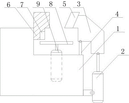
[0018] Such as figure 1 As shown, this embodiment includes a welding frame 1 and a hydraulic cylinder 2 fixed on the side wall of the welding frame 1. A baffle plate 6, a support rod 4 and a cylinder 9 are fixed on the welding frame 1. On the output end of the hydraulic cylinder 2 The movable block 3 is hinged, and the top of the support rod 4 is hinged with the bottom surface of the movable block 3, and the chuck 5 facing the baffle plate 6 is fixed on the side wall of the movable block 3, and the output end of the cylinder 9 A top plate 8 is fixed on the top, and the top plate 8 is located below the clamping area formed by the baffle plate 6 and the chuck 5; the baffle plate 6 is L-shaped, and the vertical part of the baffle plate 6 is fixed on the welding On the frame 1, the horizontal part of the baffle plate 6 faces the chuck 5, and a rectangular groove 7 with an open end is opened on the side wall of the vertical portion of the baffle plate 6 close to the chuck 5, and th...


PUM


Abstract

The invention discloses a welding fixture for a circuit board, which comprises a welding frame and a hydraulic cylinder fixed on the side wall of the welding frame, wherein a baffle, a supporting rod and a cylinder are fixed on the welding frame; the output end of the hydraulic cylinder is hinged with a movable block; the top end of the supporting rod is hinged with the bottom surface of the movable block; a chuck right opposite to the baffle is fixed on the side wall of the movable block; a top plate is fixed at the output end of the cylinder; and the top plate is located below a clamping region formed by the baffle and the chuck. During the overall circuit board welding process, lifting and fastening of the circuit board are realized through control on the cylinder and the hydraulic cylinder, the traditional circuit board fixing mode by using a bolt manually is not needed, working intensity of an operator before and after welding is greatly reduced, and due to the U-shaped clamping region formed by the chuck, the top plate and the baffle, the circuit board can be prevented from moving in the case of welding, and the welding precision of elements on the circuit board is further improved.

Description

technical field [0001] The invention relates to the field of welding of electronic components, in particular to a welding fixture for circuit boards. Background technique [0002] In the prior art, the circuit board needs to be welded accurately and firmly when welding the electrical components, so it needs to be carried out in an environment with a uniform light source. At the same time, since the circuit board needs to weld multiple electrical components, that is The circuit board needs to be fixed before welding. The usual method is to use the pressure plate and bolts to fix the circuit board, and then perform welding. Further, in order to improve the stability of the welding, the circuit board is usually fixed at multiple points, increasing the The process of the circuit board before and after welding greatly reduces the welding efficiency of the circuit board, and at the same time increases the work intensity of the operator. Contents of the invention [0003] The ob...

Claims


Application Information

Patent Timeline
Patent Type & Authority Applications(China)
IPC IPC(8): H05K3/34
CPCH05K3/34H05K2203/1509
Inventor 李胜峰
Owner SICHUAN LANXUNBAOER ELECTRONICS TECH
Why Eureka
Try Eureka