A compression spring automatic separation device

A technology of automatic separation and compression of springs, applied in centrifuges and other directions, can solve the problem that springs cannot be separated and discharged

Active Publication Date: 2018-02-16
缪小忠
View PDF10 Cites 0 Cited by
  • Summary
  • Abstract
  • Description
  • Claims
  • Application Information

AI Technical Summary

Problems solved by technology

[0004] The technical problem to be solved by the present invention: Aiming at the problem that the residual spring in the current spring automatic device cannot be separated and discharged, a new structure of compression spring automatic separation device is provided

Method used


Image

  • A compression spring automatic separation device
  • A compression spring automatic separation device

Examples


Embodiment Construction

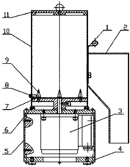
[0013] As shown in the figure, the mounting base 6, the side plate 5, and the bottom plate 4 form the installation space of the motor 3. The material cylinder 10 is installed on the mounting base 6, and the bottom of the material cylinder 10 is provided with a turntable 7. The turntable 7 is connected to the motor, and four agitators are installed on the upper surface. Cone 9. A stop pin 8 is also installed on the side wall of the barrel 10, and the stop pin 8 is slightly higher than the upper surface of the turntable 7, and the distance between the two is no more than 0.5 mm. There is a cylinder cover 11 on the top of the barrel 10, and a discharge hole is set on the side wall. A discharge adjustment door 1 and a discharge port 2 are installed outside the discharge hole. The discharge adjustment door 1 can move up and down to adjust the size of the discharge hole. It is suitable for Springs of different sizes.

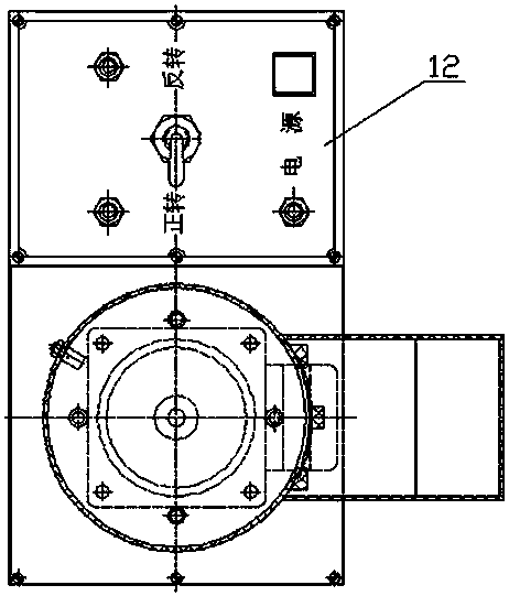
[0014] Mounting seat 6 side is provided with electrical control...


PUM


Abstract

The invention discloses an automatic separation device for a compression spring. The automatic separation device comprises a material barrel (10), a motor (3) and a rotary disc (7). Stirring cones (9) are installed on the rotary disc (7). The rotary disc (7) is installed at the bottom of the material barrel (10) and connected with the motor. A stop pin (8) is arranged at the bottom of the side wall of the material barrel (10) and located above the rotary disc (7) and the gap between the stop pin (8) and the rotary disc (7) is smaller than 0.5 mm. Due to the fact that the stop pin is additionally arranged on the combination face of the barrel wall and the rotary disc, the bottom spring collides with the stop pin, ascend and separation are accelerated, and materials are completely discharged.

Description

technical field [0001] The invention relates to a device for decoupling a compression spring. Background technique [0002] The shape of the compression spring determines that it must be entangled, interlocked, and overlapped after unpacking. If it is manually separated into individual parts during assembly, it will be time-consuming, laborious, inefficient, and affect the assembly progress. [0003] Chinese patent CN 102441500 A discloses a general-purpose compression spring automatic separator. When the compression spring rotates at high speed under the action of the turntable, it will continuously collide with the stirring cone to produce elastic plastic deformation, so that the mutual winding, overlapping and entanglement can be achieved. The compression springs are separated from each other into individual units; the separated single compression springs rotate at high speed along the inner wall of the barrel under the action of the turntable, generate centrifugal force ...

Claims


Application Information

Patent Timeline
IPC IPC(8): B04B5/12B04B15/00B04B11/00
Inventor 李忠祥杨木方
Owner 缪小忠
Why Eureka
Try Eureka