Main and auxiliary sub-mother two-stage oil cylinder multi-top injection molding top mold mechanism

A two-stage oil cylinder, mother and daughter technology, applied in the field of mold processing, can solve the problems affecting the running accuracy of the moving template, the load bearing of the rib plate, the uneven force of the ejector plate, etc. small space effect

Active Publication Date: 2018-03-27
广州一道注塑机械股份有限公司
View PDF4 Cites 0 Cited by
  • Summary
  • Abstract
  • Description
  • Claims
  • Application Information

AI Technical Summary

Problems solved by technology

[0003] The above-mentioned top mold mechanism has the following defects: (1) the number of oil cylinders is large, and the installation of the oil circuit is complicated; (2) the installation of the auxiliary ejector cylinder needs to avoid the setting of the formwork, so that the formwork needs a strong rigidity, which leads to an increase in the weight of the formwork, making the The load of the rib plate is too heavy, which affects the running accuracy of the movable formwork; (3) The force on the ejector plate is uneven, and the pressure difference of the auxiliary ejector cylinder is different, resulting in uneven force on the ejector plate, and the rigidity of the ejector plate needs to be further strengthened. It causes the ejector plate to thicken and increase in weight; (4) It is not suitable for injection machines with small spacing, fewer mold cavities, and longer preforms

Method used


Image

  • Main and auxiliary sub-mother two-stage oil cylinder multi-top injection molding top mold mechanism
  • Main and auxiliary sub-mother two-stage oil cylinder multi-top injection molding top mold mechanism
  • Main and auxiliary sub-mother two-stage oil cylinder multi-top injection molding top mold mechanism

Examples


Embodiment Construction

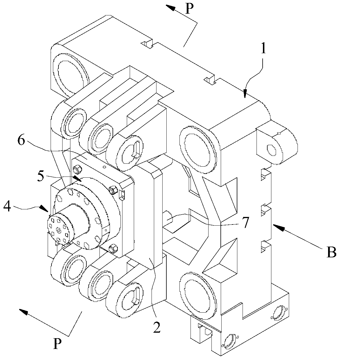
[0038] Attached below Figure 3-6 And further illustrate the technical solution of the present invention through specific examples.

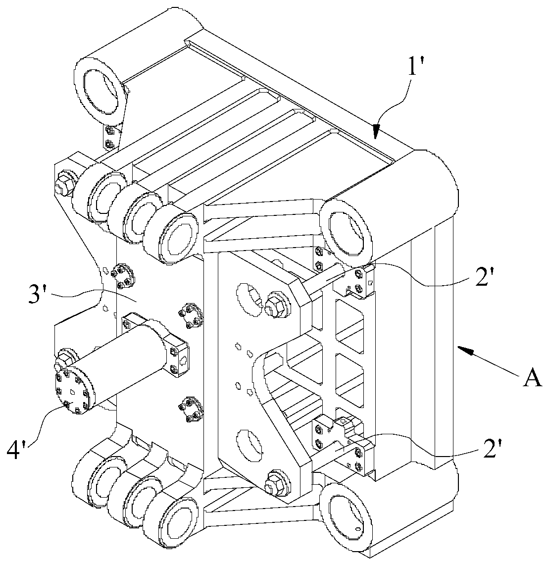
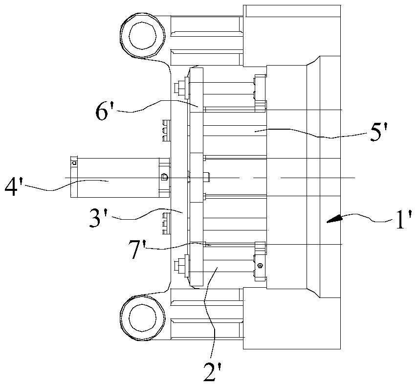
[0039] Such as Figure 3-6As shown, in the embodiment of the present invention, the main and auxiliary two-stage oil cylinder multi-top injection molding top mold mechanism includes a movable template 1 and an ejector plate 2, and the movable template 1 is connected to the ejector plate 2 through an ejector rod 3. It also includes an ejection cylinder connected with the ejection plate 2; the ejection cylinder includes a main ejection cylinder 4 and an auxiliary ejection cylinder 5, and the auxiliary ejection piston rod 51 of the auxiliary ejection cylinder 5 is a cylindrical piston rod. The inner diameter of the ejection piston rod 51 is greater than the diameter of the main ejection piston rod 41 of the main ejection cylinder 4, the auxiliary ejection piston rod 51 is coaxial with the main ejection piston rod 41, and the main ejection piston r...


PUM


Abstract

The invention discloses a multi-top type injection molding top mold mechanism with main and auxiliary two-stage oil cylinders, a plurality of ejector rods are uniformly arranged between the movable template and the ejector plate, and also include a The ejection cylinder; the ejection cylinder includes the auxiliary ejection cylinder and the main ejection cylinder. The auxiliary ejection piston rod of the auxiliary ejection cylinder is a cylindrical piston rod, and the inner diameter of the auxiliary ejection piston rod is larger than the main ejection cylinder of the main ejection cylinder. The diameter of the ejection piston rod, the auxiliary ejection piston rod is coaxial with the main ejection piston rod, and the main ejection piston rod is arranged in the auxiliary ejection piston rod, the length of the main ejection piston rod is longer than the auxiliary ejection piston rod The length of the piston rod. In the main and auxiliary two-stage oil cylinder multi-top injection molding ejector mechanism of the present invention, the main ejection piston rod is set in the auxiliary ejection piston rod, and the intermittent movement of the auxiliary ejection piston rod and the main ejection piston rod is quickly ejected. The products in the mold are ejected with large ejection force and uniform force.

Description

technical field [0001] The invention relates to the technical field of mold processing, in particular to a multi-top injection molding top mold mechanism with two stages of primary and secondary oil cylinders. Background technique [0002] The ejector mechanism is an important part of the injection molding machine for accurate and reliable ejection of products. Most of the existing injection molding machines adopt single-cylinder direct-push top mold mechanism and main and auxiliary top mold mechanism. For example, the prior art discloses a main and auxiliary multi-top injection molding top mold mechanism, such as figure 1 , 2 As shown, the ejector plate 6' is connected with the ejector rod passing through the movable formwork 1', the movable formwork 1' is provided with ribs 3', the ribs 3' are parallel to the main body of the movable formwork 1', and the ejector plate 6' is located between the rib plate 3' and the main body of the movable formwork 1', the support rod 5'...

Claims


Application Information

Patent Timeline
Patent Type & Authority Patents(China)
IPC IPC(8): B29C45/40
CPCB29C45/4005
Inventor 易恒光陈琴柯潭
Owner 广州一道注塑机械股份有限公司
Why Eureka
Try Eureka