
an automatic delivery device

A technology of automatic release and release device, which is applied in the direction of fluid pressure actuation device, fixture, mechanical equipment, etc.

Inactive Publication Date: 2017-02-01
WUHAN UNIV OF SCI & TECH
View PDF8 Cites 0 Cited by
  • Summary
  • Abstract
  • Description
  • Claims
  • Application Information

AI Technical Summary

Problems solved by technology

[0003] The purpose of the present invention is to solve the defects of existing delivery devices, and the purpose is to provide an automatic delivery device that can not only automatically deliver heavy objects, but also can deliver various items

Method used


Image

  • an automatic delivery device
  • an automatic delivery device
  • an automatic delivery device

Examples


Embodiment 1

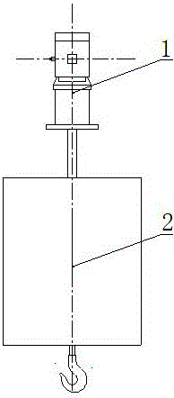
[0026] An automatic delivery device. Such as figure 1 As shown, the automatic dosing device is composed of an electro-hydraulic push rod cylinder 1 and a lower dosing device 2, the lower end of the electro-hydraulic push rod cylinder 1 and the upper end of the lower dosing device 2 are fixedly connected with the center line through threads.

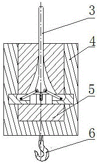
[0027] Such as figure 2 As shown, the lower feeding device 2 is made up of an inner core 3, an outer cylinder 4, an outer core 5 and a suspension hook 6. The inner core 3 is movably loaded into the outer core 5, and the outer core 5 is movably loaded into the outer cylinder 4. The lower plane of the bottom of the outer cylinder 4 is fixed with a hook 6, and the hook 6, the outer cylinder 4, the outer core 5 and the inner The extension lines of the center line of the core 3 are the same straight line.

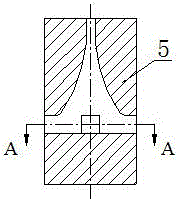
[0028] Such as image 3 and Figure 6 As shown, the outer core 5 is a cylinder, and the upper part of the cylinder is provided with ...


PUM


Abstract

The invention relates to an automatic putting device, which has the technical scheme that the automatic putting device is structurally characterized in that the lower end of an electric hydraulic push rod cylinder tube (1) and the upper end of a lower putting device (2) are fixedly connected through screw threads in a way of sharing the same center line; an inner core (3) in the lower putting device (2) is movably arranged in an outer core (5); the outer core (5) is movably arranged in an outer tube (4); the outer core (5) is a cylinder; the upper part of the cylinder is provided with a horn-shaped cavity in a way of sharing the same center line; the bottom, next to the horn-shaped cavity, of the cylinder is horizontally provided with four square through holes; the four square through holes are in cross arrangement along the radial direction. The outer tube (4) is in a cylindrical shape; the inner wall of the outer tube (4) is horizontally provided with an annular groove; the inner core (3) consists of a piston rod (7) and four lock buckles (12); the upper ends of the four lock buckles (12) are hinged to the lower end of the piston rod (7) in a center symmetry way; four slide blocks (11) of the inner core (3) are movably arranged in the annular groove of the outer tube (4) through respective corresponding square through holes in the outer core (5). The automatic putting device has the characteristics that heavy objects can be automatically put, and various objects can be put.

Description

technical field [0001] The invention belongs to the technical field of delivery devices. Specifically relates to an automatic delivery device. Background technique [0002] With the progress of society, delivery devices have been widely used in military, aviation and civilian production. However, there are some shortcomings in the existing delivery device: the ejection delivery device relies on the explosive bolt to mount and fix the delivery. By applying the ejection force to the pre-tightening of the double springs, when the delivery signal is received, the explosive bolt is energized and broken. The objects are ejected outward under the action of the double springs, but the ejection device uses the spring as the power source, which is limited by its own parameters such as the coefficient of elasticity, so it cannot release heavy objects; Block, positioning seat cap, column and other parts, but the delivery device of the basin plate assembly adopts a pneumatic method, wh...

Claims


Application Information

Patent Timeline
Patent Type & Authority Patents(China)
IPC IPC(8): F15B15/00F15B15/02F16B1/04
CPCF15B15/02F16B1/04
Inventor 涂福泉胡升谋庄羽航陈奎生吕杰曾良才欧阳惠许仁波王云学王琦琳周浩
Owner WUHAN UNIV OF SCI & TECH
Learn More